Table of Contents
Advertisement
Quick Links
Advertisement
Table of Contents

Subscribe to Our Youtube Channel
Summary of Contents for Elexa DOME DMOF1
- Page 1 Always Connected. Always Covered. On/Off Plug-In Switch DMOF1 User Manual...
-
Page 2: Preface
Preface As this is the full User Manual, a working knowledge of Z-Wave automation terminology and concepts will be assumed. If you are a basic user, please visit www.domeha.com for instructions. This manual will provide in-depth technical information about the On/Off Plug-In Switch, especially in regards to its compli- ance to the Z-Wave standard (such as compatible Command Classes, Associa- tion Group capabilities, special features, and other information) that will help you maximize the utility of this product in your system. -
Page 3: Table Of Contents
Table of Contents Preface ..........................2 Description & Features ..................... 4 Specifications ........................5 Physical Characteristics ....................6 Inclusion & Exclusion ......................7 Factory Reset & Misc. Functions ..................8 Physical Installation ......................9 LED Behavior ........................10 Button Behavior ....................... 11 Compatible Command Classes .................. -
Page 4: Description & Features
Description & Features The Dome On/Off Plug-In Switch is a Z-Wave Plus device that plugs into a standard 3-prong power outlet and lets you turn on or off any connected elec- tronic device. The On/Off Plug-In Switch also monitors how much energy the attached device uses, and reports the data to your Z-Wave Hub. -
Page 5: Specifications
Specifications Technical Specifications Radio protocol Z-Wave Plus (500 series) Power supply 110-230V AC 50/60Hz Max Current Power Consumption 0.13W Radio frequency 908.4 MHz US Z-Wave Range Up to 150’ depending on environment Dimensions (L x W x H) 1.8” x 1.8” x 1.8” Table 1 - Technical Specifications Package Contents: Thank you for purchasing the DOME... -
Page 6: Physical Characteristics
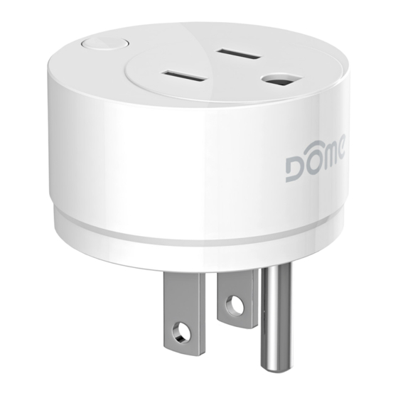
Physical Characteristics The names used in Figures 1 & 2 will be used throughout this manual. Please refer to this page as needed. DEVICE PORT PLUG BUTTON Figure 1 - On/Off Plug-In Switch Parts DMOF1 Student Edition. Figure 2 - Bottom View mic Use Only. -
Page 7: Inclusion & Exclusion
Inclusion & Exclusion Inclusion Follow the instructions for your Z-Wave Certified Conto enter inclusion mode. When prompted by the controller: 1. Plug the On/Off Plug-In Switch into an outlet 10’ from your controller. You can bring it to your desired location after the inclusion process. 2. -
Page 8: Factory Reset & Misc. Functions
Factory Reset & Misc. Functions Resetting the On/Off Plug-In Switch If needed, the On/Off Plug-In Switch can be reset locally by following these steps. Only do this when your Z-Wave controller is disconnected or otherwise unreachable. Beware that resetting your device will disconnect it from the sys- tem: 1. -
Page 9: Physical Installation
Physical Installation The On/Off Plug-In Switch can be installed in any standard 3-prong American power outlet. To control or monitor an electronic device, simply plug it into the DEVICE PORT. Make sure there is sufficient Z-Wave coverage in your desired installation location. -
Page 10: Led Behavior
LED Behavior Color Behavior This happens when… …the device powers on, but is not yet included in a Blink 5 times in 1 second Z-Wave Network. Pink …the BUTTON is pushed 3 times after the On/Off Plug-In Switch is already in a Z-Wave net- Blink 5 times in 500ms work, and the device sends a notification with its Node Info. -
Page 11: Button Behavior
Button Behavior Action Condition Result Param 10 = 1 Turn Device on or off Push Button Once Param 10 = 0 Nothing On/Off Plug-In Switch Device sends node info to Group 1 Already Included in System On/Off Plug-In Switch Push BUTTON 3 Already Included in Device is excluded from the z-Wave Network Times... -
Page 12: Compatible Command Classes
Compatible Command Classes Command Class Notes Device Reset Locally V1 (5A) Powerlevel V1 (73) Association Group Information V1 (59) Binary Switch V1 (25) All Switch V1 (27) Basic V1 (20) Returned Value: 01 05 00 07 00 07 00 Z-Wave Plus Version: 01 Role Type: 05 (Slave —... - Page 13 Command Class Notes Group 1 Group 1 is the “Lifeline” group, which can hold five devices. The On/Off Plug-In Switch sends this group a Notification Report and Bi- nary Switch Report whenever it is turned on or off. It also sends a Meter Report incrementally based on time (see Param 2,) or when a relative change in power usage is detected (see Param 6.) Finally, the On/Off Plug-In Switch sends this group a Device Reset Locally notifica-...
- Page 14 Command Class Notes When enabled (see Param 1,) the On/Off Plug-In Switch sends period updates with various usage information to Group 1 using the Meter Command Class. These reports are sent periodically (every 300s by default - see Param 2) as well as when a change in current is detected (see Param 6.) Voltage—The voltage currently being supplied by the plug (in V) Current—The current being supplied by the plug (in A)
- Page 15 Command Class Notes Returned Value: A1 42 XX XX YY YY ZZ ZZ 00 Scale/Rate Type/Meter Type/Size/Precision: A1 42 (1010 0001 0100 0010) Scale (2)—1 Rate Type—01 (Import [Consumed]) Meter Type—0 0001 (Electric Meter) Precision—010 (2 decimal places) Scale (1:0)—0 0 Size—010 (2 Bytes) Scale (Summed)—1 0 0...
-
Page 16: Configuration" Command Class Parameters
“Configuration” Command Class Parameters Configuration parameters are sent using a standard syntax to ensure interopera- bility between all manufacturers’ products. All values are represented using the hexadecimal number system. Typical syntax is as shown below. Note that the value sent must be the exact size, in bytes, as accepted by the setting. - Page 17 Param Default Size Name Available Settings Setting Sets the current level at which the On/Off Plug-In Switch will flash its LED yellow, until the current returns to below this level. It will NOT cut off current to the device; this functions as a visible warning to the user. NOTE: this value must be lower than Param 3 01 ~ Param(3) Set “Alert”...
- Page 18 Param Default Size Name Available Settings Setting Sets the time interval before the On/Off Plug-In Switch automatically shuts off. See Param 8. 00 01 ~ FF FF 00 96 Set Timer Time Interval (1 ~ 65535 in Minutes) (150 min) If this parameter is enabled, the user can turn the device on or off using the BUTTON.
-
Page 19: Troubleshooting
Troubleshooting : Q Help! My On/Off Plug-In Switch paired successfully, but my con- troller can’t see it anymore after I installed it! : A The Z-Wave signal is probably weak in that area of your home. Remember that the 120' - 150' range doesn’t take into account walls, furniture, and other obstacles. To boost your Z-Wave network coverage, add a few non-battery powered Z-Wave devices between the controller and the furthest device, like the Dome On/Off Plug or Water Main Shut-Off. -
Page 20: Warranty & Support
Household users should contact either the retailer where they Elexa Consumer Products, Inc. (”ECP”) warrants to the original purchased this product, or their government office, for details retail purchaser (”Purchaser”) that the DOME Window/Door of where and how they can take these items for sensor (the “Product”) will be free of defects in materials or...
Need help?
Do you have a question about the DOME DMOF1 and is the answer not in the manual?
Questions and answers