Table of Contents
Advertisement
Quick Links
ATN OTS-32/64
ThERmAl mulTI-PuRPOSE SySTEm
o p e r a t o r ' s m a n u a l
Important Export Restrictions! Commodities, products,
technologies and services contained in this manual are
subject to one or more of the export control laws and
regulations of the U.S. Government and they fall under the
control jurisdiction of either the US Department of State
or the US BIS-Department of Commerce. It is unlawful
and strictly prohibited to export, or attempt to export or
otherwise transfer or sell any hardware or technical data
or furnish any service to any foreign person, whether
abroad or in the United States, for which a license or written
approval of the U.S. Government is required, without
first obtaining the required license or written approval
from the Depar tment of the U.S. Government having
jurisdiction. Diversion contrary to U.S. law is prohibited.
Advertisement
Table of Contents

Subscribe to Our Youtube Channel
Related Manuals for ATN OTS-64


Summary of Contents for ATN OTS-64
- Page 1 ATN OTS-32/64 ThERmAl mulTI-PuRPOSE SySTEm o p e r a t o r ’ s m a n u a l Important Export Restrictions! Commodities, products, technologies and services contained in this manual are subject to one or more of the export control laws and regulations of the U.S.
- Page 2 (OTS-32/64, ver. 2011) Revision 1 - 2011 The information in this manual furnished for information use only, is subject to change without notice, is not to be construed as a commitment by ATN Corp. ATN Corp. assumes no responsibility or liability for any errors or inaccura- cies that may appear in this book.
- Page 3 STuDy CAREFully ThIS mANuAl BEFORE TuRNING ON AND OPERATING ThIS PRODuCT. CAuTIONS The ATN OTS-32/64 thermal multi-purpose system are preci- sion optical-electronic instruments and requires careful han- dling. To provide safe use of the systems the following instruc- tions should be observed: •...
- Page 4 WARNING Do not permanently attach the camera to dynamic-mount applica- tions that continuously transmit vibration (such as on vehicles or heavy machinery). WARNING Do not point the camera directly at any high-intensity objects that you must not view with your eyes (such as the sun or a welding arc).
- Page 5 WARNING Do not carry batteries in pockets containing metal objects such as coins, keys, etc. Metal objects can cause the batteries to short cir- cuit and become very hot. In the case of lithium batteries, a short circuit could cause them to explode. WARNING Observe battery manufacturer’s guidelines for safe handling and proper disposal of batteries.
-
Page 6: Table Of Contents
TABlE OF CONTENTS SECTION I. INTRODuCTION 1.1 General Information 1.1.1. Scope 1.1.2. Reports 1.1.3. Storage 1.1.4. Warranty Information 1.2. Description and Data 1.2.1. Description 1.2.2. OTS Standard Components 1.2.3. OTS Optional Components 1.2.4. Specifications 1.2.5. Mechanical Functions 1-11 1.2.6. Optical Functions 1-11 1.2.7. - Page 7 3.2.2. Focusing 3.2.3. Polarity and Color modes 3.2.4. Brightness 3.2.5. Recalibrate Switch 3.2.6. Zoom 3.2.7. Shut Down Operations 3.2.8. Weapon Mount Adjustment 3.2.9. Reticle patterns SECTION IV. mAINTENANCE INSTRuCTIONS 4.1. Preventive maintenance Checks and Services (PmCS) 4.1.1. Purpose of PMCS 4.1.2.
-
Page 9: Section I. Introduction
SECTION I INTRODuCTION... -
Page 10: General Information
1.1.1. SCOPE This manual contains instructions for use in operating and main- taining the ATN OTS-32/64 thermal multi-purpose systems. Throughout this manual, the ATN OTS-32/64 will be referred to as the scope or OTS. 1.1.2. REPORTS Reports from the user on recommendations for improvements are encouraged. -
Page 11: Warranty Information
ATN, at its option, will either repair or replace the product, and such action on the part of ATN shall be the full extent of ATN’s liability, and the Customer’s sole and exclusive remedy. - Page 12 Return Merchandise Authorization number (RMA). When returning please take or send the product, postage paid, with a copy of your sales receipt to our service center, ATN Corpora- tion at the address noted above. All merchandise must be fully insured with the correct postage;...
-
Page 13: Description And Data
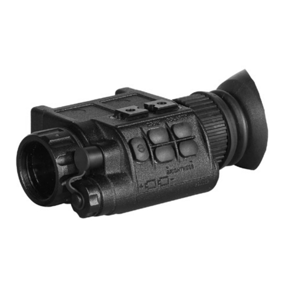
The OTS-32/64 is ideal for Border Patrol Officers, Sport Shooting Enthusiasts, Private Pro- tection, Police SWAT and Special Operations. Figure 1-1. ATN OTS Thermal Imaging Systems B. FEATuRES OTS has the following important features: •... -
Page 14: Ots Standard Components
• Rugged design with mil. spec optics • Menu functions include reticle type & color selection; wind- age & elevation adjustment • Digital brightness control • Polarity single button modes: black on white, white on black, 5 different color settings •... - Page 15 Battery CR123A Two CR123A lithium batteries used to power the unit. headmount Assembly Adjustable universal assembly that secures the ATN OTS-32/64 to the operator’s head providing hands free operation. Weapon mount System Uses for installation OTS-32/64 on a weapon using Piccatinny or Mil-STD 1913 rail and windage and eleva- tion adjustment.
-
Page 16: Ots Optional Components
Flip-up Helmet Mount ACTIOT14HMNT Dual Bridge ACTIOT14DB RCA Video/power Adapter ACTICARCA 2X Afocal Lens ACTILENSOT2X Hard Storage Case ACCSHS1610 Flip-up helmet mount Adjustable universal flip-up helmet mount assembly that secures the ATN OTS-32/64 to the operator’s helmet providing hands free operation. -
Page 17: Specifications
Dual Bridge Adapter that allows the ATN OTS-32/64 to be attached to in a binocular configuration to the head- or helmet mount. RCA Video/power adapter RCA Video/power adapter used for video transmission and to connect external power sources 2X Afocal lens Attaches to the ATN OTS-32/64 for enhanced range performance. - Page 18 < 5 sec Operating Time w/ 4+ hrs one battery pack Weatherproof Dimensions 195 x 81 x 105 mm Weight (w/bat- 0.74 kg teries) * ATN reserves the right to change the above specifications at any time without notice 1-10...
-
Page 19: Mechanical Functions
1.2.5. mEChANICAl FuNCTION The mechanical adjustments of the OTS sights allow for physical differences between individual operators using the system. The scope functions include the switchboard, refresh button, universal connector, eyepiece diopter adjustment ring, battery compartment cover, mounting rail. The mechanical controls are identified in Fig- ure 1-4. -
Page 20: Electrical Functions
1.2.7. ElECTRICAl FuNCTION The electronic circuit is powered by replaceable batteries - either two 3.0 Volt lithium battery (CR123A). Power from the batteries is supplied to the components through the OFF-ON switch button. 1-12... -
Page 21: Section Ii. Assembly And Preparation
SECTION II ASSEmBly AND PREPARATION... -
Page 22: Preparation
2.1. PREPARATION 2.1.1. PREPARATION FOR uSE This chapter contains the information necessary to prepare the scope for operation. This includes unpacking, examination for da- mage, and battery installation. A. uNPACkING The following steps must be accomplished prior to each mission where the sight is used. - Page 23 Install CR123A Lithium batteries as follows. 1. Remove the battery cap by turning it counterclockwise. 2. Check to ensure the o-ring is present. If not, replace it. 3. Observe polarity, as indicated on the outside of the battery compartment, and insert two 3.0 Volt CR123A Lithium bat- tery into the battery compartment, minus (-) end first (Figure 2-1).
-
Page 24: Assembly
2.2. ASSEmBly 2.2.1. VIDEO OuTPuT The OTS incorporates a sealed Connector used for video transmis- sion and to connect external power sources. Video Cable attaches the scope to the video facilities for video recording or video trans- mission to the external display. Connect the monocular to an external video display/recorder as follows: 1. -
Page 25: Helmet Mount
4. The OTS-32/64 headmount has a flip-up mechanism. Push the button (4) on the side of mount and lift the unit up until the unit fixates in the top position. 5. Push the same button (4) to lower OTS-32/64 to the viewing position. -
Page 26: Dual Bridge Adapter
4. Loosen screw (3). Push button (2) and insert the bracket of the OTS into rail (4) of the helmet mount. 5. Place the helmet with OTS onto head. 6. Loosen the screw (3) and move the unit for proper eye relief adjustment. -
Page 27: Afocal Lens
2. Push the clamps (2) on the front of adapter. 3. Slide the unit rearwards until the alignment boss aligns with the alignment groove (3) on the adapter. Push until the unit locks into the adapter. 4. Repeat for second unit. For detachment the unit push the clamps on the front of adapter and slide the unit forwards. -
Page 28: Weapon Mount
2.2.6. WEAPON mOuNT To mount the ATN OTS-32/64 on the weapon perform the follow- ing: 1. Mount the weapon mount adapter (1) onto the Elcan mount system (2) with two screws M4x7. 2. Slightly loosen the mounting screw (3) on the side of weapon mount adapter. -
Page 29: Section Iii. Operation
SECTION III OPERATION... -
Page 30: General Information
3.1. GENERAl INFORmATION 3.1.1. GENERAl This section contains instructions for operation of OTS. The func- tion of controls and indicators is explained. CAuTION The OTS scope is a precision electron-optical instrument and must be handled carefully at all times. 3.1.2. CONTROlS AND INDICATION The OTS scope is designed to adjust for different users and cor- rects for most differences. - Page 31 CONTROlS AND ITEmS FuNCTIONS INDICATORS RECALIBRATE Cover front lens with cap or hand and push SWITCH Button button to recalibrate image. Objective Lens Fixed focus. Focus Diopter Adjustment Focuses eyepiece lens without the need for glasses. Adjusts for sharper image of intensifier screen.
-
Page 32: Operating Procedure
To turn the unit on press the button labeled ON/OFF. After a warm-up time of approximately 5 seconds, video of the ther- mal scene appears. Figure 3-2. Switchboard of ATN OTS-32/64 3.2.2. FOCuSING To focus the scope you need to adjust the diopter first. The scope has an adjustable eyepiece with a range of +2 to -6 diopter. -
Page 33: Polarity And Color Modes
3.2.3. POlARITy AND COlOR mODES Push quickly to switch to between white hot and black hot. Hold down to turn on and cycle through color modes. 3.2.4. BRIGhTNESS Press «BRIGHTNESS +» and «BRIGHTNESS –» buttons for bright- ness adjustment. Each short push of the buttons «BRIGHTNESS +»... -
Page 34: Weapon Mount Adjustment
3.2.8. WEAPON mOuNT ADJuSTmENT The vertical and horizontal positions of the reticle want to be cen- tered in their respective travel range. Typically this initial zero is then adjusted to the desired point of impact for the chosen ammu- nition. The self-centering refers to the position of the reticle in the scopes field of view not its position relative to the optical axis. -
Page 35: Reticle Patterns
Beyond 200 Yards Disengage BCL (2) and use Mount’s MVA (3) to acquire range. Fine tune using scope’s internal adjustment. 3.2.9. RETIClE PATTERNS The ATN OTS-32/64 does not have a field user on/off button to acti- vate the aiming reticle. To change the pattern contact to the service center. -
Page 37: Section Iv. Maintenance Instructions
SECTION IV mAINTENANCE INSTRuCTIONS... -
Page 38: Preventive Maintenance Checks And Services (Pmcs)
4.1. PREVENTIVE mAINTENANCE ChECkS AND SERVICES (PmCS) 4.1.1. PuRPOSE OF PmCS PMCS is performed daily when in use to be sure that the sight is ready at all times. Procedures listed in Table 4-1 are a systematic inspection of OTS that will enable you to discover defects that might cause the sight to fail on a mission. - Page 39 NOT Fully mIS- SEq. ITEm TO ChECkING PROCEDuRE SION ChECk CAPABlE IF: Objective Check to ensure the objec- Objective lens Lens tive lens is not loose. loose. Rubber Rubber Eye-cup Inspect for cuts or tears. Eye-cup torn or cut. AFTER ChECkING PROCEDuRES Replace protective covers on the lenses.
-
Page 40: Troubleshooting
4.2. TROuBlEShOOTING 4.2.1. GENERAl This section contains information for locating and removal most of the OTS operating troubles which may occur. Each malfunction for an individual component or assembly is followed by a list of tests or inspections that will help determine probable causes and corrective action to take. -
Page 41: Maintenance Procedures
PROBlEm PROBABlE CAuSE CORRECTIVE ACTION The brightness The batteries has a Replace the batteries. of the image low voltage. on the screen Factory alignment Send the scope to the ser- is low. broken. vice center. 4.3. mAINTENANCE PROCEDuRES 4.3.1. SCOPE mAINTENANCE The OTS maintenance consists of external inspection of its com- ponents for serviceability, cleaning and installation of the stan- dard and optional accessories. -
Page 42: Preparing For Extended Storage
lens holder and changing cotton swab after each circular stroke. Repeat this step until the glass surfaces are clean. B. ClEANING OF ACCESSORIES Clean accessories with a soft brush (cloth) and soap and water as required. CAuTION Dry thorougly each item before replacing into the storage case. - Page 43 B. REmOVAl AND INSTAllATION OF ChINSTRAP 1. Remove the chinstrap (Figure 4-2) by unsnapping the Wel- cro tape from the left side of the headband. Unbuckle the chinstraps from narrow strap assembly. 2. Replace the chinstrap by using the Welcro tape on the left side of the headband.
-
Page 44: Appendix A. Spare Parts List
APPENDIX A SPARE PARTS lIST The Spare Parts List is an illustrated catalog of main parts and assemblies completing the OTS system. Therefore, in case of failure of any part or assembly User could replace it by ordering the corresponding part/assembly from the Spare Parts List. - Page 45 PART NO. DESCRIPTION FIG. ITEm qTy AT 88831.004 Screw AT 88831.005 Rail AT 88831.006 Eye Piece AT 88831.007 Rubber Eye-cup AT 88831.008 Battery Cap AT 88831.009 Connector Cap Figure A-2. OTS-32/64 Accessories Table A-2. OTS-32/64 Acceessories parts list PART NO. DESCRIPTION FIG.
- Page 46 PART NO. DESCRIPTION FIG. ITEm qTy AT 88839.000 Weapon Mounting System AT 88841.000 Flip-up Helmet Mount AT 88842.000 Dual Bridge AT 88843.000 Afocal 2X Lens AT 88843.000 Wrist Strap Figure A-3. headset Assembly Table A-3. headset Assembly PART NO. DESCRIPTION FIG.
- Page 47 Figure A-4. helmet mount Assembly Table A-4. helmet mount Assembly PART NO. DESCRIPTION FIG. ITEm qTy AT 88841.0001 Screw AT 88841.0002 Mount Assembly Figure A-5. Weapon mounting System Table A-5. Weapon mounting System PART NO. DESCRIPTION FIG. ITEm qTy AT 88839.0001 Weapon mount adapter AT 88839.0002 Elcan mount system...
- Page 48 For customer service and technical support, please contact American Technologies Network Corp. North American Office: 1341 San Mateo Avenue South San Francisco, CA 94080 phone: 800-910-2862, 650-989-5100 fax: 650-875-0129 www.atncorp.com ©2011 ATN Corporation...
Need help?
Do you have a question about the OTS-64 and is the answer not in the manual?
Questions and answers