Table of Contents
Advertisement
Quick Links
Revisions ........................................................................................................................................... 1
1 Specifications ................................................................................................................................. 2
1.1 Performance Parameter ....................................................................................................... 2
1.2 Indicator .............................................................................................................................. 4
1.3 Dimensions.......................................................................................................................... 4
1.4 Standard Flange ................................................................................................................... 5
1.5 Pinout Description ............................................................................................................... 5
2 Modbus-RTU Control .................................................................................................................... 6
2.1 Wiring ................................................................................................................................. 6
2.2 Default Communication Parameters ................................................................................... 6
2.3 Modbus-RTU Description ................................................................................................... 7
2.3.1 RTU Framing ........................................................................................................... 7
2.3.2 Supported Modbus Function Code ........................................................................... 7
2.3.3 Register Mapping ..................................................................................................... 7
2.3.4 Register Description ................................................................................................. 9
2.3.4.1 Initialization .................................................................................................. 9
2.3.4.2 Force .............................................................................................................. 9
2.3.4.3 Position ........................................................................................................ 10
2.3.4.4 Speed ........................................................................................................... 10
2.3.4.5 Initialization State ....................................................................................... 11
2.3.4.6 Gripper State ............................................................................................... 11
2.3.4.7 Current Position .......................................................................................... 12
2.3.4.8 Save Parameter ............................................................................................ 12
2.3.4.9 Initialization Direction ................................................................................ 12
2.3.4.10 Slave Address ............................................................................................ 13
2.3.4.11 Baud Rate .................................................................................................. 13
2.3.4.12 Stop Bits .................................................................................................... 14
2.3.4.13 Parity ......................................................................................................... 14
2.3.4.14 Test I/O Parameters ................................................................................... 15
2.3.4.15 I/O Mode Switch ....................................................................................... 15
2.3.4.16 I/O Parameter Configuration ..................................................................... 16
3 I/O Control ................................................................................................................................... 18
3.1 Wiring ............................................................................................................................... 18
3.2 I/O Setting ......................................................................................................................... 19
3.2.1 Configure IO .......................................................................................................... 19
3.2.2 Open IO .................................................................................................................. 20
PGC-300 Gripper
Short Manual
Content
Advertisement
Table of Contents

Related Manuals for DH PGC-300

Summary of Contents for DH PGC-300
-
Page 1: Table Of Contents
PGC-300 Gripper Short Manual Content Revisions ............................1 1 Specifications ..........................2 1.1 Performance Parameter ....................... 2 1.2 Indicator ..........................4 1.3 Dimensions.......................... 4 1.4 Standard Flange ........................5 1.5 Pinout Description ....................... 5 2 Modbus-RTU Control ........................6 2.1 Wiring ..........................6 2.2 Default Communication Parameters ................... - Page 2 3.2.3 Save Settings ......................21 3.2.4. Restart ........................21...
-
Page 3: Revisions
Revisions Date Version Revised content First edition, write wiring instructions and 20200426 V1.0 command instructions Change some instructions , Update the description 20200904 V2.0 of IO mode... -
Page 4: Specifications
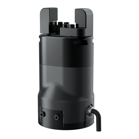
Fingertips can be customized: Fingertips can be replaced according to situation, which is suitable for precision machining, parts assembly, and other fields. Figure 1.1 PGC series gripper 1.1 Performance Parameter The specific parameters of PGC-300 gripper are listed in Table 1.1. - Page 5 Fz, the x-axis direction torque is Mx, the y-axis direction torque is My, and the z-axis direction torque is Mz. The PGC-300 finger load table is shown in Table 1.2: Figure 1.2 Finger load diagram Table 1.2 PGC-300 Torque Table .
-
Page 6: Indicator
·Object dropped state: Green light blinking. 1.3 Dimensions The gripper hardware parameters contain the specific size of the gripper, the mounting hole, as shown in Figure 1.3(a), Figure 1.3(b). Figure 1.3 (a) Dimension drawing of PGC-300 Figure 1.3 (b) Dimension of PGC-300 guide rail... -
Page 7: Standard Flange
1.4 Standard Flange The flange is used for the connection between PGC-300 electric gripper and robot. The company provides standard flange, as shown in Figure 1.4. The gripper also supports custom flanges. Figure 1.4 Standard flange according to ISO 9409-1-50-4-M6 1.5 Pinout Description... -
Page 8: Modbus-Rtu Control
2 Modbus-RTU Control 2.1 Wiring Use the provided RS-485 to USB converter (see the schematic in Figure 1.1 below) to plug into a PC or other Controllers. Figure 2.1 RS485 Connection Warning ·Please check the connector before inserting, and do not forcibly insert the plug. Even if the cable connector has a fool-proofing design, but you can still forcibly insert it, then the gripper would be damaged. -
Page 9: Modbus-Rtu Description
2.3 Modbus-RTU Description 2.3.1 RTU Framing This gripper uses the standard Modbus-RTU protocol. In RTU mode, the first field is the device address. The allowable characters transmitted for all fields are hexadecimal 0 ... 9, A ... F. Networked devices monitor the network bus continuously, including during the silent intervals. - Page 10 Basic control registers: initialization, force setting, reference position, speed, and some states. Configuration registers: gripper’s parameter configuration. Includes Modbus communication parameters and I/O parameters. Table 2.2 Basic Control register map high- low- Function order order Description Write Read byte byte 0x01:initialization;...
-
Page 11: Register Description
2.3.4 Register Description 2.3.4.1 Initialization This register is used to initialize the gripper. Write: If write 1 (0x01 hex) to this register, the gripper will be initialized (fingers move to the minimal or maximum position. The initialization direction depends on the value of initialization direction register). -
Page 12: Position
Read the closing force currently set (read): Send: 01 03 01 01 00 01 D4 36 Return: 01 03 02 xx xx crc1 crc2 2.3.4.3 Position This register is used to set the reference position of gripper's fingers, then the fingers will move to the position immediately. -
Page 13: Initialization State
Return: 01 03 02 xx xx crc1 crc2 2.3.4.5 Initialization State This register is used to store current initialization state of gripper, you can get the initialization state by reading this register. The address is 0x0200. The description of this register is shown in Table 2.8. Table 2.8 Initialization State Function Address... -
Page 14: Current Position
2.3.4.7 Current Position This register is used to store the Actual position of the Gripper. The address is 0x0202. The description of this register is shown in Table 2.10. Table 2.10 Current Position Function Address Description Write Read Current actual Current Gripper actual position 0x0202... -
Page 15: Slave Address
Table 2.12 Baud Rate Function Address Description Write Read Configure 0: Open,1:Close Baud Rate 0x0301 initialization Current setting (default: 0) direction The value of this register is 0 by default. If the register value is 0, when you send the initialization command, the gripper finger will open and find the maximum position. -
Page 16: Stop Bits
Table 2.14 Baud Rate Function Address Description Write Read 0-5:115200,57600, Configure gripper Baud Rate 0x0303 38400,19200,9600, Current setting Modbus Baud rate 4800(default: 0) The value of this register is 0 by default, corresponding to a baud rate of 115200. Example: Set gripper baud rate to115200 (write): Send: 01 06 03 03 00 00 79 8E... -
Page 17: Test I/O Parameters
Send: 01 06 03 05 00 00 99 8F Return: 01 06 03 05 00 00 99 8F 2.3.4.14 Test I/O Parameters This register is used to test the I/O Parameters. The address is 0x0400. The description of this register is shown in Table 2.17. Table 2.17 I/O Control Function Address... -
Page 18: I/O Parameter Configuration
Set the I/O control mode switch off (write): Send: 01 06 04 02 00 00 29 3A Return: 01 06 04 02 00 00 29 3A NOTE ·If you just need to control the gripper through Modbus RTU, you should write 0 to this register and save all parameters to turn off the I/O control mode. - Page 19 Continuous multiple address write(write)[Group 1:1000 ‰ position;20%force;10%speed Group 2:100 ‰ position;20%force;2%speed Group 3:0 ‰ position;100%force;5%speed Group 4:592‰position;100%force;10%speed]: Send: 01 10 0405 000C 18 03e8 0014 000A 0100 0014 0002 0000 0064 0005 0250 0064 000a 9f 44 Return: 01 10 04 05 00 0C D1 3D...
-
Page 20: O Control
3 I/O Control The I/O mode is a common control method in industry. The grippers will monitor the pin states of Input 1 and Input 2 (0V and high resistance states). For these two pins, there will be four logic states:00,01,10,11. You can control this gripper through changing the states of Input 1 and Input 2. -
Page 21: I/O Setting
Input pin should be connected to the Controller’s Output pin. Table 3.3 wire Description Wire color Description White 485_A Brown 485_B OUTPUT 1 Green Yellow OUTPUT 2 24 V Grey Pink INPUT 2 INPUT 1 Blue 3.2 I/O Setting The diagram of IO operation steps is as follows: Step 1: Step 2: Step 3:... -
Page 22: Open Io
Figure 3.1 (a) graphical configuration Figure 3.1 (b) test software register configuration The second way: You can use continuous multiple register write 10 (HEX): Send: 01 10 0405 000C 18 03e8 0014 000A 0100 0014 0002 0000 0064 0005 0250 0064 000a 9f 44 Receive: 01 10 04 05 00 0C D1 3D 3.2.2 Open IO... - Page 23 3.2.3 Save Settings Save the configured parameters, and write 01 at the register of 0x300 for saving. Send: 01 06 03 00 01 48 4e Return: 01 06 03 00 01 48 4e 3.2.4. Restart After power off, you can connect the input and output to the corresponding equipment, and power on after confirming that the wiring is correct.
Need help?
Do you have a question about the PGC-300 and is the answer not in the manual?
Questions and answers