Table of Contents
Advertisement
Quick Links
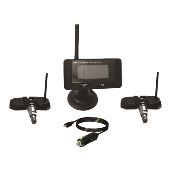
Key Features:
Visual and audible warnings
Set desired PSI level
Mounts to windshield or
dashboard
Valve stems pictured may differ from stems packed in kit.
Thank you for purchasing Dill TPMS Trailer Kit. Properly inflated
tires increase fuel economy, reduce tire wear and increase han-
dling. A warning system to notify you of an underinflated tire will
help give you time to respond prior to potentially damaging your
tire or trailer.
For more information visit our website at http://www.trailertpms.com
1502
Alerts when tire pressure is too low
Alerts when tire pressure is too high
Alerts when tire temperature is too high
Advertisement
Table of Contents

Related Manuals for Dill 1502

Summary of Contents for Dill 1502
- Page 1 Valve stems pictured may differ from stems packed in kit. Thank you for purchasing Dill TPMS Trailer Kit. Properly inflated tires increase fuel economy, reduce tire wear and increase han- dling. A warning system to notify you of an underinflated tire will help give you time to respond prior to potentially damaging your tire or trailer.
-
Page 2: Table Of Contents
Table of Content Page 1. Setting Up the System 1.1 Transmitter Installation 1.2 Install the Display 1.3 Setting the Baseline (Cold Inflation) Pressure 1.4 Using the External Antenna—RF Interference 2. Transmitter Installation: 3. System Overview 3.1 System Components 3.2 How the System Works 3.3 Normal Monitoring Warnings 3.5 Display Indicator and Controls... -
Page 3: Setting Up The System
1.0 Setting Up the System 1.1 Transmitter Installation Have a professional tire retailer install the valves with transmitters in the wheels. See section 2 for details. Each transmitter has a unique ID and needs to be installed in the same corresponding position as noted in Figure on page 13. -
Page 4: Using The External Antenna-Rf Interference
The display is now in learn mode and will store the cold inflation pres sure of each tire once it receives a signal from it. The process may take up to 8 minutes. If all pressures are not received in 8 minutes, the dis play will shift back to the monitoring mode. - Page 5 Remove the original antenna from the back of the display unit and replace it with the coaxial wire antenna via display connector. Install the magnet/antenna at the rear of the vehicle, which will give it the nearest proximity to the transmitters. Thus, increasing signal reception between the display/receiver and transmitters.
-
Page 6: Transmitter Installation
2.0 Transmitter Installation Before installation into the rim hole, you must assemble the transmitter and valve stem together. 2.1 Unscrew the hex nut and remove the metal washer from the valve stem. 2.2 Place the valve stem onto the transmitter and use the lock washer & screw to hold valve stem against the transmitter body. -
Page 7: System Overview
2.10 Apply soap suds or commercial leak detection solution on the valve tip, grommet / rim seal. If no leakage is found, install the valve cap. Other wise, re-inspect and resolve leak issue. 2.11 Dynamically balance the wheel before it is put back on the vehicle. FIGURE 5 3.0 System Overview The TPMS trailer kit monitors tire pressure and temperature. - Page 8 FIGURE 7 The display is preprogramed to provide a warning if the pressure drops 20% below or 30% above the cold inflation pressure. It will also give a high temperature warning if the temperature exceed 176°F. The high temperature warning point is not adjustable. The system is shipped with the baseline (cold inflation) pressure set at 35 psi.
-
Page 9: Normal Monitoring
3.3 Normal Monitoring 3.3.1 Stationary State: The transmitter will transmit tire pressure and temperature data to the display at 2-minute intervals. As the data is received, the display will refresh. 3.3.2 Moving State: The inertial switch of transmitter is on when the speed exceeds 16mph. - Page 10 3.4.3 High Temperature Warning When the temperature in a tire exceeds 176°F, the following will oc- cur: 1. The display will show the temperature of the abnormal tire and the digits will flash. 2. An audible alert warning sound will be heard. 3.
-
Page 11: Display Indicator And Controls
3.5 Display Indicator and Controls FIGURE 8 SET BUTTON R/D BUTTON Used to set number of wheel positions Used to learn tire cold inflation pressure High Temp Icon Wheel >176° Positions Pressure Temperature 3.6 Transmitter Components FIGURE 9 SCREW ELECTRONIC LOCK TRANSMITTER WASHER... -
Page 12: Tire Rotation
3.7 Tire Rotation Every transmitter has a unique 8 character ID that is associated with a chip in the display. An alpha label is also added to each transmitter and chip as an additional identifier. As tires are moved side to side, the chips are moved to the corresponding position in the display. -
Page 13: Wheel Position Numbers
3.8 Wheel Position Numbers Wheel positions are number as illustrated below. FIGURE 11 (LEFT) (RIGHT) 2 Wheels... -
Page 14: Specifications
4. Specifications 4.1 Transmitter Weight: 1.25 oz. (35g) Dimensions: 0.59” x 2.50” x 1.11” (1.5 x 2.8 x 6.4 cm) Operating Temperature Range: -40°F to 257°F (-40°C to 125°C) Pressure Accuracy: ±2PSI (±.14Bar) Temperature Accuracy: ±5.4°F (±3°C) ... -
Page 15: Component Part Numbers
4.3 Component Part Numbers PART NUMBER DESCRIPTION TPMS DISPLAY UNIT, MOUNT & POWER 1502-2 CORD 9300 TPMS TRANSMITTER AND CHIP 1905 SIGNAL BOOSTER 4.4 Available Valve Configurations WHEEL RIM HOLE SIZE: .453” P/N: TP 416 WHEEL RIM HOLE SIZE: .625”... - Page 16 Dill Air Controls Products 1500 Williamsboro Street Oxford, North Carolina 27565 Trailer Kits—Tire Pressure Monitoring Systems Customer Service: 800-815-3455 www.dillvalves.com ~ Quality Automotive Products Since 1909 ~ Revision B 1504-6 (E04641)
Need help?
Do you have a question about the 1502 and is the answer not in the manual?
Questions and answers