Advertisement
INTERFACE SERIES
Installation & Operation Instructions
AIM2
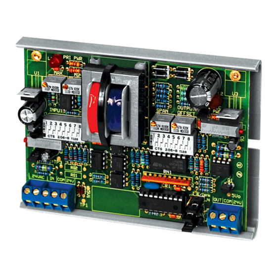
GENERAL INFORMATION
The AIM2 optically isolates an analog (voltage
or
current)
input
corresponding output signal. It will accept
any input signal between 0 and 20 VDC, or 0
and 20 mA, and output any signal within
those ranges. The AIM2 has preset or
adjustable inputs and preset or adjustable
outputs that can be either voltage or current.
The current signals on the input or output can
be either sink or source. The AIM2 requires
one external 24 VAC isolation transformer
with oating secondary for power. It has an
onboard 24 VAC isolation transformer to
supply power to the isolated output. The
AIM2 is eld calibratable, however, factory
calibration is available upon request for an
additional charge. This will speed up
installation time for the end user.
MOUNTING INSTRUCTIONS
Ground yourself to discharge static electricity
before touching any electronic equipment, as
some components are static sensitive. The
interface device can be mounted in any position. If circuit board slides out of snap track, a non-conductive
"stop" may be required. Use only ngers to remove board from snap track. Slide out of snap track or push
up against side of snap track and lift that side of the circuit board to remove. Do not flex board. Do not
use tools.
WIRING INSTRUCTIONS
PRECAUTIONS
• Remove power before wiring. Never connect or disconnect wiring with power applied.
• When using a shielded cable, ground the shield only at the controller end. Grounding both
ends can cause a ground loop.
• This device needs to have its own Isolated Transformer. This transformer cannot be
connected/or shared with any other device. It is recommended you use an isolated UL-listed class
2 transformer.
• All wiring must comply with all local and National Electric Codes.
Automation Components, Inc.
2305 Pleasant View Road | Middleton, WI 53562
Phone: 1-888-967-5224 | Website: workaci.com
signal
from
its
FIGURE 1: DIMENSIONS
3.23"
(81.90mm)
3.25"
(8255mm)
4.69" (119.13mm)
Page 1
Phone: 1-888-967-5224
Website: workaci.com
4.60" (116.84mm)
I
0.70"
(17.78mm)
Version: 9.0
I0000585
Advertisement
Table of Contents

Related Manuals for aci AIM2

Summary of Contents for aci AIM2
- Page 1 (81.90mm) outputs that can be either voltage or current. The current signals on the input or output can be either sink or source. The AIM2 requires one external 24 VAC isolation transformer with oating secondary for power. It has an onboard 24 VAC isolation transformer to supply power to the isolated output.
- Page 2 FIGURE 2: WIRING Power 24 VAC Source Current or Source Current or Voltage Output Signal Voltage Input Signal Sink (Loop Powered) Current Output Sink (Loop Powered) Current Input Connections using External VDC Supply Connections using Internal VDC Supply Set Jumper For Sink Current Sink Current Input Sink...
-
Page 3: Step 1) Wiring Connections
The AIM2 is factory set as follows, unless otherwise speci ed: All DIP switches are set to OFF and will not produce a proper signal output. Be sure to set switches to your required input and output ranges before powering. See “SETTING AIM2 INPUT” below. - Page 4 2.) Apply the maximum of the input signal to terminals IN and COM. With a volt meter measure the voltage from TP1 to the AIM2’s input side common (COM). Turn the input Max. pot until the meter reads 5.00 ± 0.00 V.
-
Page 5: Power Up And Checkout
The AIM2 will now operate to your speci cations, or the standard settings from the factory. If no eld calibrations were made, then the AIM2 will accept a 0 to 5 volt DC input signal and produce an isolated and proportional 0 to 5 volt DC output signal. -
Page 6: Product Specifications
-20 to 150°F (-28.9 to 65.5°C) WARRANTY The AIM2 Series is covered by ACI’s Two (2) Year Limited Warranty, which is located in the front of ACI’S SENSORS & TRANSMITTERS CATALOG or can be found on ACI’s website: www.workaci.com. Page 6 Automation Components, Inc. - Page 7 NOTES Page 7 Automation Components, Inc. Version: 9.0 2305 Pleasant View Road | Middleton, WI 53562 I0000585 Phone: 1-888-967-5224 | Website: workaci.com...
- Page 8 Automation Components, Inc. 2305 Pleasant View Road Middleton, WI 53562 Phone: 1-888-967-5224 Website: workaci.com Page 8 Automation Components, Inc. Version: 9.0 2305 Pleasant View Road | Middleton, WI 53562 I0000585 Phone: 1-888-967-5224 | Website: workaci.com...
Need help?
Do you have a question about the AIM2 and is the answer not in the manual?
Questions and answers