Table of Contents
Advertisement
Quick Links
User's Manual
Digital Signal Processors
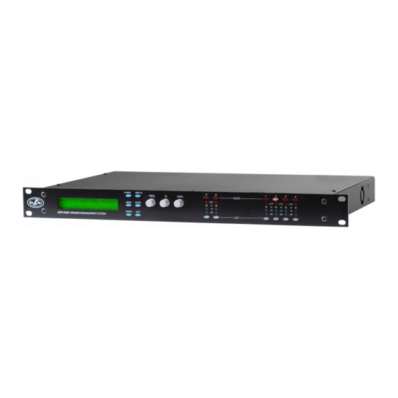
DSP-2040
Antes de utilizar el equipo, lea la sección
"Precauciones de seguridad" de este manual.
Conserve este manual para futuras consultas.
Before operating the device, please read the
"Safety precautions" section of this manual.
Retain this manual for future reference.
Advertisement
Table of Contents

Related Manuals for D.A.S. DSP-2040

Summary of Contents for D.A.S. DSP-2040
- Page 1 User's Manual Digital Signal Processors DSP-2040 Antes de utilizar el equipo, lea la sección “Precauciones de seguridad” de este manual. Conserve este manual para futuras consultas. Before operating the device, please read the “Safety precautions” section of this manual. Retain this manual for future reference.
- Page 2 DSP-2040 Precauciones de Seguridad Safety Precautions El signo de exclamación dentro de un triángulo indica la The exclamation point inside an equilateral triangle is intended to existencia importantes instrucciones operación alert the users to the presence of important operating and mantenimiento en la documentación que acompaña al producto.
- Page 3 DSP-2040 GARANTÍA Todos nuestros productos están garantizados por un periodo de 24 meses desde la fecha de compra. Las garantías sólo serán válidas si son por un defecto de fabricación y en ningún caso por un uso incorrecto del producto.
- Page 4 DSP-2040 DECLARACIÓN DE CONFORMIDAD DECLARATION OF CONFORMITY DAS Audio Group, S.L. C/ Islas Baleares, 24 - 46988 - Pol. Fuente del Jarro - Valencia. España (Spain). Declara que DSP-2040 Declares that DSP-2040 Cumple con los objetivos esenciales de las Directivas: Abide by essential objectives relating Directives: de Baja Tensión (Low Voltage Directive)
-
Page 5: Table Of Contents
DSP-2040 Contents Introduction Front panel description Rear panel description Operating the device Editing audio parameters - Input channels Editing audio parameters - Output channels Input ganging and output ganging Memory structure Security and locking Advanced audio features Specifications User’s Manual... - Page 6 DSP-2040 User’s Manual...
-
Page 7: Introduction
DSP-2040 Introduction The DSP-2040 are powerful DSP based audio processors, ideally suited for install applications, where they combine the functions of a multitude of conventional products in a compact 1U unit. To achieve this, the units have up to two inputs and four outputs which can be configured in a selection of basic crossover modes –... -
Page 8: Front Panel Description
DSP-2040 Front panel description [1]-LCD Screen: Shows, by default, the name of the last recalled memory on the bottom line of the screen, and the current routing on the top line. Also used to show all parameters as they are edited, and all menu selections. -
Page 9: Rear Panel Description
DSP-2040 Rear panel description [1]: Power Switch: turns the unit’s mains supply off and on. Mains Fuse: located in a finger-proof holder adjacent to the mains inlet. A spare fuse is also located in this holder. Mains Inlet: connected via a standard IEC socket. -
Page 10: Operating The Device
DSP-2040 Operating the device The following operating information covers setup and control of the DSP-2040 via the front panel controls only. Start-up procedure Switching on the unit will display a brief message detailing the unit type and software version running and all LEDs will briefly illuminate. - Page 11 DSP-2040 Routing Options and Processing Blocks Due to the completely new DSP platform, the routing possibilities within the DSP-2040 has been made completely flexible, with a matrix available allowing any combination of inputs to be routed to any output. The additional DSP power has permitted the inclusion of more processing blocks, even considering the extra inputs and outputs, and the doubling of sample rate.
- Page 12 DSP-2040 2 x 2 way crossover: As shown, each input feeds a pair of outputs, odd numbers being the low frequency split, and even numbers being the high part of the spectrum. Default crossover frequencies are shown by each output.
- Page 13 DSP-2040 1 x 4 way crossover: Inputs A is fed to all four outputs, with input B unused. The crossover points can be adjusted as desired. Note: Input B will be muted and cannot be unmuted. OUTPUT 1: 15Hz - 149Hz OUTPUT 2: 149Hz - 1.31kHz...
- Page 14 DSP-2040 Free Assign Routing If none of the preset configurations are appropriate to the required system setup, it is possible to manually select the routing of the crossover. This is achieved through the ‘Crossover Menu’ -> ‘Design A Crossover’. Pressing ENTER will start the crossover design wizard, with the first option being to choose the routing.
-
Page 15: Editing Audio Parameters - Input Channels
DSP-2040 Editing audio parameters - Input channels Input gain The range of the control over the input gain is -40dB to +6dB in 0.1dB steps. Pressing EDIT, the display shows: Input A Gain Input Gain = +6.0dB Use the GAIN allow to change its value. Pressing ENTER to confirm. -
Page 16: Editing Audio Parameters - Output Channels
DSP-2040 Editing audio parameters - Output channels Output gain The range of the control over the output gain is -40dB to +15dB in 0.1dB steps. Pressing EDIT the display shows: Output 1 Gain Output Gain = +6.0dB Output polarity The polarity (or phase) of each output may be switched individually as below. - Page 17 DSP-2040 Output high pass filter The high pass crossover filter on each output has a frequency range of <10Hz up to 32kHz in 1/36th Octave steps. If you try to set the high pass filter to a higher frequency than the low pass (which would be pointless and result in no output), the message ‘High/Low Freq.
- Page 18 DSP-2040 Information: Note that 2 bands each will be lost when using 48dB slope crossover filters, resulting in a maximum of 5 bands of EQ when both high and low pass are set to 48dB/Octave. Output limiter The limiter on each output has adjustable attack and threshold, with a release time that is selectable to be a multiplier of the attack time.
-
Page 19: Input Ganging And Output Ganging
DSP-2040 Input ganging and output ganging The method of linking inputs or outputs together during editing is achieved in the same way, so only crossover (output) ganging will be explained here. Having selected ‘Crossover Ganging’ from the menu under the ‘Crossover Sub-menu’... -
Page 20: Memory Structure
DSP-2040 Memory structure The DSP-2040 has its memories split into sections, allowing independent recall of crossover settings (i.e. all parameters associated with outputs), and input settings. There are, therefore, two types of memory available: ‘Input Only’ and ‘Crossover Only’,also combinations ‘Input & Xover’. - Page 21 The DSP-2040 has 256 memory locations, but these are dynamic in nature – obviously a memory containing Input and Crossover settings takes up more space than one containing just Input settings.
-
Page 22: Security And Locking
DSP-2040 Security and locking After selecting the Security Sub Menu and pressing ENTER, select one of the lock types, choosing the most appropriate one for your application. As ever, ENTER will confirm your selection. User Specific Upon pressing ENTER to select this type of lock, each parameter group is presented in turn. Choose the type of lock (as above) using the FREQ encoder, and press ENTER to confirm each parameter. - Page 23 DSP-2040 Unlocking the Unit To unlock the unit press ENTER and then type the code in. This can be entered by using the FREQ control to select a character, and the BACK and NEXT keys to move to the next character. Alternatively, the EDIT keys can be used to enter a code by pressing any combination of the eight buttons.
-
Page 24: Advanced Audio Features
DSP-2040 Advanced audio features Program Limiter High performance digital limiters are provided for each output with control over attack time, release time and threshold parameters - see details below. This level of control allows the user to balance the required subjective quality of the limiter against the driver protection requirements. - Page 25 DSP-2040 “D-Max” Clip Limiter The main limitation with traditional dynamics control is the inability of the processing to react truly instantaneously to the signal. One of the most significant advantages of digital signal processing over analogue is the ability to delay the audio signal precisely and without extensive complex hardware. The entire...
- Page 26 DSP-2040 The DSP-2040's “D-Max” limiter predelays the sidechain signal, resulting in a “zero overshoot” limiter, which is able to catch all peaks and provide a reliable absolute maximum setting for the output of any channel. The predelayed sidechain is shown in green, with the main signal in red.
- Page 27 DSP-2040 Setting Accurate Limiter Thresholds The limiters built into the DSP-2040 are intended to be used for loudspeaker driver protection, as opposed to amplifier protection. All modern professional power amplifiers designed for live sound use have their own limiters, which are tailored to protecting the amplifier from clipping.
- Page 28 DSP-2040 Crossover Filter Slopes It should also be noted that the turnover frequency displayed on the screen is the -3dB point for all types except Linkwitz-Riley where the -6dB point is shown. If the -6dB point is to be used for the Bessel or Butterworth filter, take the required crossover frequency, multiply this by the appropriate factor from the following table and then select the closest available frequency on the display.
- Page 29 DSP-2040 Parametric Filter Types and Their Uses A wide selection of filter types has been made available under the PEQ section when editing input or output filters. Scrolling through the various filter types is achieved by repeated presses of the ENTER key.
- Page 30 DSP-2040 <- Low/High pass variable ‘Q’ filter (low pass shown) InA Input A LPF:1~~\ 1k00Hz Q = 3.0 LPF VarQ Remember – to change filter types, press BYPASS to bypass the filter, and then use ENTER to select the filter type.
-
Page 31: Specifications
DSP-2040 Specifications Inputs: 2 electronically balanced Limiters Impedance: > 10k ohms. Program Limiter: CMRR : >65dB 50Hz - 10kHz. Threshold: +22dBu to -10dBu MUTE : ON/OFF Attack time: 0.3 to 90 milliseconds Outputs: 4 electronically balanced Release time: 2/4/8/16/32 x Attack time Source Imp: <... - Page 32 www.dasaudio.com DAS Audio Group, S.L. DAS Audio of America, INC. DAS Audio Asia PTE. LTD. DAS do Brasil LTDA. C/. Islas Baleares, 24 6900 NW 52th Street 3 Temasek Avenue, Centennial Rua Dos Andradas, 382 SL 46988 Fuente del Jarro Miami, FL.
Need help?
Do you have a question about the DSP-2040 and is the answer not in the manual?
Questions and answers