Table of Contents

Related Manuals for Proteus 500 Series

Summary of Contents for Proteus 500 Series
- Page 1 Proteus Industries Inc. SERIES METERING FLOW SWITCHES TECHNICAL REFERENCE MANUAL Proteus 5-Year Warranty A full statement of our warranty is available on our website at www.proteusind.com/warranty/. 500TRM-002 Page 1 of 22 March 2007...
-
Page 2: Table Of Contents
Table of Contents Page 1. Introduction 2. Features and functions 3. How the flow sensor works 4. Specifications and performance 5. Product certifications 6. Installation 7. Selecting Trip Points 8. Measuring Flow Rate 9. Digital Displays 10. Cleaning and Maintenance 11. -
Page 3: Introduction
Calibrated 0-5VDC output The 500 Series’ is calibrated to provide a 5 VDC output for 2.0 or 4.5 GPM (7.5 or 17 LPM). Actual flow rate can be determined by attaching a voltmeter. An optional scaleable digital voltmeter can be calibrated to provide a direct local display of flow rate. - Page 4 The distance between the 500 Series pipe or fitting connections is identical to those of previous Proteus flow sensors. Weighing only 16.8 oz (470 g), the metering flow switch can be mounted directly to your pipe or tubing. Mounting lugs are located at the place of previously used panel mounting screws. The 500 Series metering flow switch can be panel mounted with two screws and appropriate standoffs.
- Page 5 • LED provides instant status information. Like a traffic signal, the green, amber and red lights indicate flow status so that problems are easily detected. Green, amber and red lights provide instant inidication of the status the flow switch and the flow rate.
-
Page 6: How The Flow Sensor Works
Hall-effect sensor Section 3 How the flow sensor works Magnets The rotor spins when liquid flows through the meter. Magnets in the rotor switch a Hall-effect sensor mounted in the meter body. Rotor The resulting pulse train is converted by the electronics to a voltage that is proportional to the linear velocity at which the liquid flows through the meter. -
Page 7: Specifications And Performance
Section 4 Specifications and performance The most current information on the performance capability of these sensors is accessible on the Proteus website at www.proteusind.com. Flow Range 0.15 - 2.0 0.3 – 4.5 0.6 – 7.5 1.2 – 17.0 Connections Part Number... -
Page 8: Product Certifications
Pipe or tubing mounting If rigid piping or tubing is used, the 500 Series metering flow switch may be supported by direct connection to the pipe or tubing. - Page 9 Table 2: Minimum ID of pipe or connection for calibrations to be valid. Note The flow response of 500 Series sensors and thus their calibration may be dependent on the form of the device attached to the inlet connection and other closely located up-stream devices.
- Page 10 Mounting the device with the flow connections uppermost can help eliminate entrained air from your system. Flow Direction The 500 Series Metering Flow Switch is not sensitive to flow direction. Flow can be introduced to the sensor from either side. NPT pipe thread connections Pipe threads seal by making metal-to-metal contact between male and female components.
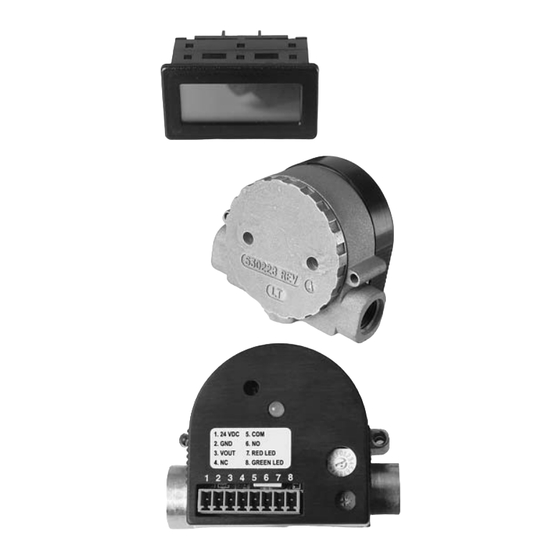
- Page 11 If fluid temperatures will be outside the range of 0 - 85°C, the electronics package must be mounted remotely from the sensor. Remote mounting may require customized changes to the sensors. Please contact Proteus Applications for additional information. Electrical Connections Note Only personnel familiar with the electrical circuit and control functions of the system in which the sensor is to be included should perform installation of this product.
-
Page 12: Selecting Trip Points
Tool Required: A fine flat screwdriver 1. Identify the Part Number of the 500 Series metering flow switch being adjusted. This is noted on the product label. 2. Select the Trip Point Flow chart that applies to your metering flow switch. - Page 13 6. Check that the indicator of the fine adjustment potentiometer is pointed towards the 12 o’clock position. If necessary, use the screwdriver to turn the fine adjustment potentiometer so that the indicator is pointed towards the 12 o’clock position. 7. With the screwdriver, turn the 16-step switch so that its indicating arrow points towards the selected position switch position.
- Page 14 3.89 3.89 3.90 3.92 3.94 3.97 4.01 4.05 4.10 4.16 4.24 4.16 4.16 4.17 4.18 4.20 4.24 4.27 4.32 4.37 4.43 4.50 Table 3: 500 Series trip point flow selection chart - GPM. 500TRM-002 Page 14 of 22 March 2007...
- Page 15 14.6 14.6 14.7 14.7 14.8 14.9 15.0 15.2 15.8 15.6 15.9 15.7 15.7 15.7 15.8 15.9 16.0 16.1 16.3 16.9 16.7 16.9 Table 4: 500 Series trip point flow selection chart - LPM. 500TRM-002 Page 15 of 22 March 2007...
-
Page 16: Measuring Flow Rate
Section 8 Measuring Flow Rate The voltage output by the 500 Series metering flow switches allows the flow rate of the liquid passing through the device to be estimated. While the flow response curves of the 500 Series metering flow switches are extremely linear, they do NOT pass through zero, requiring the use of a linear regression formula or calibration graphs to derive the actual flow rate from the measured output voltage. -
Page 17: Digital Displays
0.3 – 4.5 0G504D 1.2 – 17.0 0L504D Table 5: Part Numbers and flow ranges for Digital Displays for 500 Series Note Switches and potentiometers have been set to fit the range of your devices. Changing these settings may invalidate the calibration! -
Page 18: Cleaning And Maintenance
Wiring connections for Digital Display ection 10 Cleaning and Maintenance Maintenance of the 500 Series Metering flow switch is normally limited to cleaning the chamber in which the rotor spins and an annual recalibration. leaning the 500 Series flow sensor... - Page 19 Cleaning the 500 Series Flow Sensor 1. Turn OFF the liquid flow in your flow circuit and remove the 500 Series sensor from your system. Place the sensor on a clean surface. Remove the faceplate from the sensor body using a face-spanner wrench.
- Page 20 7. Inspect the O-ring to ensure that it is not brittle, cracked or otherwise damaged. If necessary replace with a #132 O-ring of a material compatible with the liquid being passed through the flow meter. Position the O-ring on the inner rim of the faceplate.
-
Page 21: Calibration & Recalibration
Calibration & Recalibration Note 500 Series sensors are calibrated at Proteus with water at temperatures ranging from 22 to 28C. Changes in fluid type can alter the calibrated response of the sensor. Large changes in liquid temperature can alter the calibrated response of the sensor. -
Page 22: Replacement Parts
® Nylon, Real-Tuff and Hercules are trademarks of their respective holders 500 Series electronics are sensitive to Electro Static Discharge. There is normally no need to open the electronics case, but if it is opened, proper ESD precautions should be taken.
Need help?
Do you have a question about the 500 Series and is the answer not in the manual?
Questions and answers