
Related Manuals for Tigo TSB-10-US

Summary of Contents for Tigo TSB-10-US
- Page 1 Tigo Energy Intelligence Tigo Energy Intelligence Battery Storage Installation and Operation Manual 002-00085-00 | 10/22/2021 P a g e Tigo Energy, Inc. www.tigoenergy.com support@tigoenergy.com...
-
Page 2: Disclaimer
If further information is required, a Tigo sales office should be consulted. Sale of the product shown in this document is subject to the terms and conditions outlined in the Tigo warranty or other contractual agreement between Tigo and the purchaser. -
Page 3: Table Of Contents
Wiring the EI Battery ........................... 21 Battery expansion ........................... 21 DC Conductors ............................ 22 Communication cable ......................... 22 Connecting the EI Battery to the EI Inverter ................... 23 DC conductors ............................. 24 P a g e Tigo Energy, Inc. www.tigoenergy.com support@tigoenergy.com... - Page 4 After Installation ............................30 Cleaning and Care ........................... 30 Maintenance ............................30 Troubleshooting ............................30 Your Tigo Customer Support contact ...................... 30 Decommissioning ............................32 Packing the battery ..........................32 Storing the EI Battery ..........................32 Disposing of the battery .......................... 32 Warranty ..............................
-
Page 5: Safety Symbols
AVIS est utilisé pour traiter des pratiques non liées aux blessures corporelles. On the battery enclosure: Symbol Explanation Risk of electrical shock Risque d'électrocution Risk of burn injuries Risque de brûlures Observe the operating instructions Respectez les instructions de service P a g e Tigo Energy, Inc. www.tigoenergy.com support@tigoenergy.com... -
Page 6: Safety Information
Use only copper conductors, solid or stranded. Never use fine stranded conductors. All conductors must have a minimum temperature rating of 75°C. P a g e Tigo Energy, Inc. www.tigoenergy.com support@tigoenergy.com... -
Page 7: Ei Residential Solution Overview
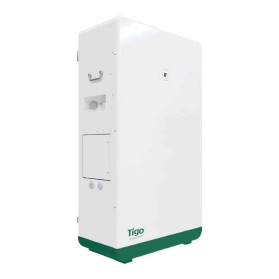
EI Residential Solution Overview The Tigo Energy Intelligence (EI) Battery provides energy resilience in the event of a grid outage and optimizes energy consumption based on rate plans for today’s home energy needs. The Tigo EI Battery is the energy storage component of Tigo’s Energy Intelligence Solution. -
Page 8: Transportation And Storage
Installation of the equipment can take place concurrently, although the EI Inverter is the hub of all equipment in this system. Where a workstream can split off from the main efforts of battery installation a QR code will be provided directing to the appropriate product’s documentation. P a g e Tigo Energy, Inc. www.tigoenergy.com support@tigoenergy.com... -
Page 9: Pre-Installation
Sleeve anchor Wire ferrule Safety-lock screws Figure 2 Package contents Note: The battery modules are shipped separately from the EI Battery enclosure. Three battery modules are installed in each EI Battery enclosure. P a g e Tigo Energy, Inc. www.tigoenergy.com support@tigoenergy.com... -
Page 10: Tools & Items Needed For Installation
3) Base wire box 14) Mounting tabs 4) Disconnect switch 9) Front cover 15) Heat sink 5) DC knockout 10) LED indicator 6) Power button 11) Base front cover 10 | P a g e Tigo Energy, Inc. www.tigoenergy.com support@tigoenergy.com... -
Page 11: Ei Battery Labels
Battery Specifications Safety Labels Model Number & Specifications Certifications Tigo EI App Figure 5 Safety label Figure 4 Specifications label inverter connection wire box The battery enclosure has a wire box door on each side. The includes two labels specifying the battery output terminals for connection to the inverter and the communications ports. -
Page 12: Ei Battery Weight And Dimensions
When multiple EI Batteries are being installed, consider the conduit path between the right Battery expansion wire box sides of any two battery enclosures. The (12) is located on the right side and the expansion connections occur between these wire boxes. 12 | P a g e Tigo Energy, Inc. www.tigoenergy.com support@tigoenergy.com... -
Page 13: Installation Requirements
If installing multiple battery enclosures, the battery expansion cables should not exceed a length of 6ft-7in. Space enclosures accordingly. The minimum clearances shown below must be observed. Figure 9 Clearances 13 | P a g e Tigo Energy, Inc. www.tigoenergy.com support@tigoenergy.com... -
Page 14: Installation
EI Battery and rotate the mounting tabs 90º to the outside. Figure 10 Mounting tabs 2) Mark holes through the mounting tabs for drilling. Drill 2in (5cm) deep holes with an 8mm bit. Figure 11 Mounting preparation 14 | P a g e Tigo Energy, Inc. www.tigoenergy.com support@tigoenergy.com... -
Page 15: Removing The Front Cover
The front cover has a grounding wire and display cable attached to the interior. Use caution and detach wires before carefully attempting to remove the cover. Figure 14 Front cover removal 15 | P a g e Tigo Energy, Inc. www.tigoenergy.com support@tigoenergy.com... -
Page 16: Battery Module Installation
The battery cables are pre-installed and labeled inside the enclosure. These cables are tied inside the enclosure. These cable ties will need to be cut in order to make the required connections. Figure 16 Battery modules 16 | P a g e Tigo Energy, Inc. www.tigoenergy.com support@tigoenergy.com... -
Page 17: Wiring The Batteries
The battery modules are connected in series by the Link-In and Link-Out communications cables. • The battery modules are wired together for power using the BAT+ and BAT- conductors. 17 | P a g e Tigo Energy, Inc. www.tigoenergy.com support@tigoenergy.com... -
Page 18: Upper Battery
5) Connect the lower inner BAT + plug to the lower inner battery red terminal labeled +. Figure 20 Lower 6) Connect the lower inner BAT - plug to the lower inner battery battery modules 18 | P a g e Tigo Energy, Inc. www.tigoenergy.com support@tigoenergy.com... - Page 19 Remember to plug in the display cable and reconnect the EGC. The 6 front cover screws should be torqued to 1Nm. 19 | P a g e Tigo Energy, Inc. www.tigoenergy.com support@tigoenergy.com...
- Page 20 Wire Wire Lower outer BAT Link-out Lower outer BAT Link-out BAT 3 BAT 6 Lower Outer Lower Outer Lower outer BAT Link-in Figure 22 Battery module expansion wiring diagram 20 | P a g e Tigo Energy, Inc. www.tigoenergy.com support@tigoenergy.com...
-
Page 21: Wiring The Ei Battery
2) Install 2 conduits from the right side of Primary to the right side of Secondary for the DC conductors and communication cable. Use appropriate conduit fittings to provide a water-tight seal. Figure 24 EI Battery expansion preparation 21 | P a g e Tigo Energy, Inc. www.tigoenergy.com support@tigoenergy.com... -
Page 22: Dc Conductors
7) Connect the CAT5/6 cable to the CAN/COM terminal in the battery expansion wire box primary EI Battery’s (12). 8) At the secondary battery enclosure, the CAT5/6 cable enters the Figure 28 CAN/COM label 22 | P a g e Tigo Energy, Inc. www.tigoenergy.com support@tigoenergy.com... -
Page 23: Connecting The Ei Battery To The Ei Inverter
Connect two conduits from the battery enclosure to the inverter. Use appropriate water-tight fittings. Figure 30 Inverter connection preparation 23 | P a g e Tigo Energy, Inc. www.tigoenergy.com support@tigoenergy.com... -
Page 24: Dc Conductors
T568A and T568B. 7. Insert the RJ-45 connector into the INV Figure 34 INV-COM label COM port. 8. Once complete, replace the wire box covers and torque the screw to 1Nm. 24 | P a g e Tigo Energy, Inc. www.tigoenergy.com support@tigoenergy.com... -
Page 25: Commissioning
Commissioning The EI Battery uses the Tigo EI mobile App to commission the system. If not already downloaded on a mobile device, scan the QR code to access the latest EI app for Android and iOS. This QR code is also located on the side of the battery on the specifications label. -
Page 26: Torque Table
Energy Intelligence App. This communication occurs between the mobile device and the EI Inverter. The inverter communicates all settings/modes of operation to the EI Battery. 26 | P a g e Tigo Energy, Inc. www.tigoenergy.com support@tigoenergy.com... -
Page 27: Led Status
Alarm state Power ≤50%, LED B1/2 are on, LED B3/4 are off Ring Power ≤75%, LED B1/2/3 are on, LED B4 are off Power >75%, LED B1/2/3/4 are on 27 | P a g e Tigo Energy, Inc. www.tigoenergy.com support@tigoenergy.com... -
Page 28: Powering Off The Ei Solution
2. Open/turn off the AC disconnect switch between inverter and the service entrance. 3. Open/turn off the DC disconnect switch at the bottom of the inverter. 4. Power off the battery 28 | P a g e Tigo Energy, Inc. www.tigoenergy.com support@tigoenergy.com... -
Page 29: Forced Start/Shutdown
3) Wait 10 seconds and confirm the LEDs indicate the system is entering the Standby state. Inverter connection wire box 4) Turn OFF the BAT-switch in the (8). Replace the Power button cover when complete. 29 | P a g e Tigo Energy, Inc. www.tigoenergy.com support@tigoenergy.com... -
Page 30: After Installation
Contacting technical support may be required to assist with your installation or maintenance. If the system is commissioned, Tigo will have component-level data to help understand and resolve the issue. If the PV modules are not monitored, or the inverter is not communicating, additional information will be required. - Page 31 • Module Imp • Number of modules in each string The Tigo Customer Support Team can be contacted in multiple ways: • Chatting with a Customer Support tech through the EI App. • Submitting a ticket directly in the Tigo EI mobile App.
-
Page 32: Decommissioning
20°C to 45°C). Disposing of the battery Do not dispose of any battery or accessory with household waste. Comply with local and state regulations for disposing of electronic waste. 32 | P a g e Tigo Energy, Inc. www.tigoenergy.com support@tigoenergy.com... -
Page 33: Warranty
Warranty The warranty of the EI Battery is 10 years or 6,000 cycles, whichever occurs first. The warranty document can be found at https://www.tigoenergy.com/product/ei-battery 33 | P a g e Tigo Energy, Inc. www.tigoenergy.com support@tigoenergy.com... -
Page 34: Specifications
Specifications 34 | P a g e Tigo Energy, Inc. www.tigoenergy.com support@tigoenergy.com...
Need help?
Do you have a question about the TSB-10-US and is the answer not in the manual?
Questions and answers