Table of Contents
Advertisement
Quick Links
Laser cutting system hardware user manual
RuiDa Technology Co., Ltd
Addr:
202-203,B-Block,Technology
Avenue,Nanshan
Province,P.R.China
Tel:
0755--26066687
Fax:
0755--26982287
E-mail:
sales@rd-acs.com
Web:
www.rd-acs.com
SHENZHEN RUIDA TECHNOLOGY
RDC6334G Laser cutting system hardware user manual
Read this manual before operation
The content include of electric connections and operating steps
Read the manual to operate the systems
RDC6334G
Building,NO.,1057
District,Shenzhen
city,Guangdong
Nanhai
https://www.ruidacontroller.com
Advertisement
Table of Contents

Summary of Contents for RD RDC6334G
- Page 1 RDC6334G Laser cutting system hardware user manual Read this manual before operation The content include of electric connections and operating steps Read the manual to operate the systems RDC6334G Laser cutting system hardware user manual RuiDa Technology Co., Ltd...
- Page 2 RDC6334G Laser cutting system hardware user manual COPYRIGHT All rights reserved.You may not reproduce, transmit, store in a retrieval system or adapt thispublication, in any form or by any means, without the prior written permissionof RuiDa, except as allowed under applicable copyright laws. We have identifiedwords that we consider as trademarks.
- Page 3 RDC6334G Laser cutting system hardware user manual CERTIFICATION DECLARATION The product has been certified by the CE (Commutate European) safety certification. It has passed the corresponding conformity assessment procedure and the manufacturer's declaration of conformity, in accordance with the relevant EU directive.
- Page 4 RDC6334G Laser cutting system hardware user manual SAFETY INFORMATION When using this system, please make sure the operation is correct and the usage is safe. Some signs or text will be used to remind you to pay attention to the dangerous matters and some important information.
- Page 5 RDC6334G Laser cutting system hardware user manual Sign in、Devanning、Examine cargo The product itself with plastic or metal shell, can protect the external electrical components from damage. The products are packed in foam bags and anti-static bags. If there is any external damage to the package, check the equipment and notify the carrier and carrier in writing of the damage.
-
Page 6: Table Of Contents
RDC6334G Laser cutting system hardware user manual Contents Chapter 1 Brief introduction of HMI and keys function................1 1.1 HMI..............................2 1.2 Introduction of key function......................2 Chapter 2 Main interface and functions introduction................3 2.1 Boot interface.............................4 2.2 Main interface............................ 5 2.3 speed setting............................ -
Page 7: Hmi
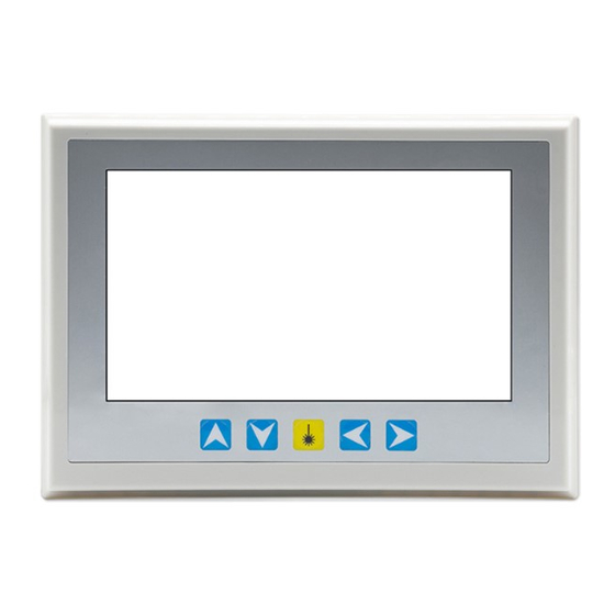
RDC6334G Laser cutting system hardware user manual Section 1 Brief introduction of HMI and keys function CONTENTS: Introduction of key function SHENZHEN RUIDA TECHNOLOGY... - Page 8 RDC6334G Laser cutting system hardware user manual 1.1 HMI Figure 1.1 HMI 1.2 Key function introduction “Reset”: Reset the motherboard “Origin”: Set locating point “Laser”: Laser on/off “Track”: To track current processing file “File”: memory document and U disk file management ...
- Page 9 RDC6334G Laser cutting system hardware user manual “Esc”: To stop working and cancel file preview when suspend working “Enter”: To set layer parameter SHENZHEN RUIDA TECHNOLOGY...
-
Page 10: Chapter 2 Main Interface And Functions Introduction
RDC6334G Laser cutting system hardware user manual Section 2 Main interface and functions introduction CONTENTS: Boot interface Main interface Speed setting Max/Min power settings Layer parameter setting SHENZHEN RUIDA TECHNOLOGY... -
Page 11: Boot Interface
RDC6334G Laser cutting system hardware user manual 2.1 Boot interface Boot screen will display when system is resetting as shown below: Figure 2.1 Boot screen Boot screen could be modified by users, by importing defined picture via PC software and then download. -
Page 12: Main Interface
RDC6334G Laser cutting system hardware user manual 2.2 Main interface Main interface will display when system reset is complete as shown below: Coordinates display area: The laser head coordinates display in this area during file processing or manual operation. Graphics display area: This area is used for file preview and processing to trace the movement of the laser tube. -
Page 13: Speed Setting
RDC6334G Laser cutting system hardware user manual layer is in the highlighted state, press “Enter” to access layer parameter modification interface. In the state of system idle, users can perform file processing, parameter setting, file preview and other operations. 2.3 Speed setting Press “Speed”... -
Page 14: Max/Min Power Settings
RDC6334G Laser cutting system hardware user manual Figure 2.3-2 Press number keys to enter a new value, press “Enter” to confirm the input. Press "Esc" to cancel the input and return to the previous interface, press "Del" to delete the current value. -
Page 15: Layer Parameter Setting
RDC6334G Laser cutting system hardware user manual Figure 2.4-2 Refer to speed setting for parameter setting method. 2.5 Layer Parameter Setting When system is idle, when there is layer information, click layer parameter list with your finger or mouse to select a layer. If there are multiple layers, you can press and hold the middle of the list and drag down with your finger. - Page 16 RDC6334G Laser cutting system hardware user manual parameters. The panel will prompt “parameter setting successful”, then press “Enter” to return main interface. When modifying another layer parameter without closing the current layer setting window, be sure to save the current layer parameter first (if needed). Then click the "Layer List Box" and the layer list pops up, select the layer to be modified, and then modify the parameters of the layer.
-
Page 17: Chapter 3 Menu Functions
RDC6334G Laser cutting system hardware user manual Section3 Menu functions CONTENTS: System information System Configuration Functions Users parameter Vendor parameter Axis Reset Settings SHENZHEN RUIDA TECHNOLOGY... -
Page 18: System Information
RDC6334G Laser cutting system hardware user manual 3.1 System information Click the “System information” button in the main interface of “Menu”, a dialog box will pop up as following: Figure 3.1 Click “Read parameters” button, panel will read and display the information of motherboard. Click “Reset”... - Page 19 RDC6334G Laser cutting system hardware user manual Figure 3.2-1 Press “Read Parameters” to read the parameters after entering this interface. Press the “Write Parameters” button to save the modified parameters on the motherboard. Press the “Esc” button to close dialog box and return back to previous interface.
-
Page 20: Functions
RDC6334G Laser cutting system hardware user manual Figure 3.2-3 Click “communication interface select box” to choose “USB” or “Ethernet”, and press the “Enter” button to save the parameters after selecting. Close the dialog box and return back to previous interface; press “Esc”... - Page 21 RDC6334G Laser cutting system hardware user manual At the column of Origin Point setting, red box on the left of the option means forbidden, green box means enable, you can click to switch back and forth. Parameters are saved before closing the dialog box automatically The remaining operations are the same as above.
- Page 22 RDC6334G Laser cutting system hardware user manual When choose “Set as default parameters”, system will set all the current manufacturer parameters and user parameters as default parameters. After the entry is pressed, a password is required. When choose “Recover default parameters”, system will overwrite all current user parameters and manufacturer parameters with the default parameters set before.
-
Page 23: Vendor Parameter
RDC6334G Laser cutting system hardware user manual Operations are the same as above. Please refer to the mainboard manual for the description of each parameter. 3.5 Vendor Parameter Click the “Vendor parameters” button in the main interface of “Menu”, a dialog box will pop up as following: Pic 3.5... - Page 24 RDC6334G Laser cutting system hardware user manual Figure 3.6 Operations are the same as above. SHENZHEN RUIDA TECHNOLOGY...
- Page 25 RDC6334G Laser cutting system hardware user manual Section 4 File functions CONTENTS: Memory files U disk files SHENZHEN RUIDA TECHNOLOGY...
-
Page 26: Memory Files
RDC6334G Laser cutting system hardware user manual 4.1 Memory files Click the “file” button in the main interface, a dialog box will pop up as following: Figure 4.1-1 When entering this interface, the system memory file will be read automatically, the file name and the number of processed pieces will be displayed on the list, and the selected file will be previewed in the preview area on the right. - Page 27 RDC6334G Laser cutting system hardware user manual Figure 4.1-2 After click the “File Preview” button, the file will be previewed in the main interface, all the current dialog boxes will be closed automatically, and click “Cancel” button in the main interface to cancel preview...
- Page 28 RDC6334G Laser cutting system hardware user manual Figure 4.1-3 The operations in this interface are the same as above. SHENZHEN RUIDA TECHNOLOGY...
-
Page 29: U U Disk Files
RDC6334G Laser cutting system hardware user manual 4.2 U disk files Click “U Disk” button on the menu of “File” to pop up U disk file list, as shown below: Figure.2 The operations in this interface are the same as above. -
Page 30: Alarm Information
RDC6334G Laser cutting system hardware user manual Section 5 Alarm information CONTENTS: Alarm information SHENZHEN RUIDA TECHNOLOGY... - Page 31 RDC6334G Laser cutting system hardware user manual 5.1 System error Some alarm information will pop up during users operation or system operations, e.g. water protection failure, hard limit protection, track out of bounds, etc. Here’s an example: The system has a water protection failure, as shown below: Figure 5.1...
- Page 32 RDC6334G Laser cutting system hardware user manual Section 6 Installation size CONTENTS: Installation size SHENZHEN RUIDA TECHNOLOGY...
-
Page 33: Installation Size
RDC6334G Laser cutting system hardware user manual 6.1 Installation size Unit: mm Figure 6.1 SHENZHEN RUIDA TECHNOLOGY... - Page 34 RDC6334G Laser cutting system hardware user manual Thank you for your selection of our production! All the copyright of this manual is owned by Ruida technology. Any person or company can not copy upload and send the manual without Ruida’s permission.
Need help?
Do you have a question about the RDC6334G and is the answer not in the manual?
Questions and answers