Table of Contents
Advertisement
Quick Links
Advertisement
Table of Contents

Subscribe to Our Youtube Channel
Related Manuals for maxxess eMAX-MR62e

Summary of Contents for maxxess eMAX-MR62e
- Page 1 OSDP READER INTERFACE MODULE Installation Guide and Specifications This device complies with FCC Part 15, Class A Specifications. The device meets CE Specifications, and is RoHS Certified. February 2019 This device is UL 294 Recognized.
-
Page 2: Table Of Contents
TABLE OF CONTENTS Paragraph Title Page No. General …………………………………………………………………………………………….. 3 eMAX-MR62e Hardware ……………………………………………….……………………...… 4 eMAX-MR62e Terminal Blocks & Jumpers …………..…………………………………...… 5 Bulk Erase Configuration Memory ……………………………………………………………. 6 Input Power ……………………………………………………………….……………………….. 7 Communication Wiring …………………………………………………………………………. 7 OSDP Reader Wiring …………………..……………………………………………………….. 7 Input Circuit Wiring ………………………………………….………………………………….. -
Page 3: General
Input circuits can be configured as unsupervised or supervised. The eMAX-MR62e requires PoE, PoE+ or local 12 Vdc for power. The eMAX-MR62e may be mounted in a 3-gang switch box with the mounting plate that is supplied with the unit. Or it can be mounted in a standard Maxxess enclosure. -
Page 4: Emax-Mr62E Hardware
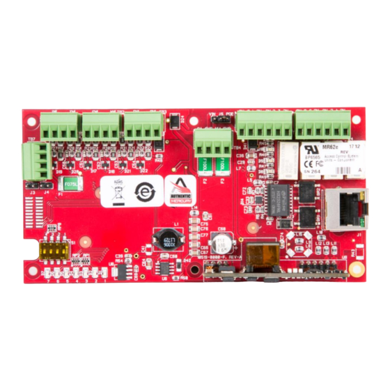
Hardware: J3: TAMPER TO OSDP SWITCH READERS 2.75 [69.85] Ø.125 [3.18] .2 [5.08] 2.35 [59.69] 6 PLACES GND TR- TR+ S1: DIP SWITCH STATUS LEDs INPUTS 12 Vdc IN & AUX POWER J4: TIA-485 OUTPUT TERMINATION JUMPER J5: INPUT... -
Page 5: Emax-Mr62E Terminal Blocks & Jumpers
Terminal Blocks and Jumpers: MR-51E CONNECTIONS TB1-1 Input 1 TB1-2 TB1-3 Input 2 TB1-4 TB2-1 Input 3 TB2-2 TB2-3 Input 4 TB2-4 TB3-1 Input 5 TB3-2 TB3-3 Input 6 TB3-4 Auxiliary Power Output – 12 Vdc TB4-1 TB4-2 Auxiliary Power Output Ground Input Power –... -
Page 6: Bulk Erase Configuration Memory
MR62e will power up using the OEM default communication parameters. 5. LEDs 1 and 2 alternately flash at a 0.5 second rate while the memory is being erased. 6. Once the memory is eased, LED 1 will be on for about 3 seconds, then the eMAX-MR62e will reboot. -
Page 7: Input Power
1-pair cable of sufficient gauge must be used for power. See specification section. The RS-485 termination jumper, J4, is only installed if the eMAX-MR62e is at one end of the communication bus. Only devices at each end of the communication bus are terminated. Never install termination to more than two devices on the communication bus. -
Page 8: Input Circuit Wiring
For this reason, it is recommended that a diode be used to protect the relay. Wire should be of sufficient gauge to avoid voltage loss. It is possible for the eMAX-MR62e to provide power for a 12 Vdc door strike providing the maximum current is not exceeded. See specification section. -
Page 9: Status Leds
LED is off. 11. IT Security When installing When installing the eMAX-MR62e, it is important to ensure that it is done in a secure manner. Upon installation, the user accounts to the web configuration page should be created with secure passwords, and that all DIP switches are in the off position for the normal operating mode. -
Page 10: Specifications
12. Specifications: The eMAX-MR62e is for use in low voltage, Class 2 circuits only. Power Input: PoE (12.95 W), compliant to IEEE 802.3af PoE+ (25 W), compliant to IEEE 802.3at 12 Vdc 10 %, 1.7 A maximum For UL, the Power Sourcing Equipment (PSE) such as a PoE/PoE+ enabled network switch and/or PoE/PoE+ power injectors must be UL Listed under UL294B. -
Page 11: Additional Mounting Information
Graybar part number 88158404 ▪ Magnetic switch set: G.R.I. part number: 505 Side View: OPTIONAL BLANK COVER W/SCREWS OPTIONAL MAGNETIC TAMPER SWITCH MR51e WITH INCLUDED MOUNTING PLATE OPTIONAL 3-GANG JUNCTION BOX TO ETHERNET FIELD WIRING NETWORK February, 2019 eMAX-MR62e-Man Page 11 of 16... -
Page 12: Warranty And Liability
This product is not intended for, nor is rated for operation in life-critical control applications. Maxxess Systems is not liable under any circumstances for loss or damage caused by or partially caused by the misapplication or malfunction of the product. Maxxess Systems liability does not extend beyond the purchase price of the product. -
Page 13: Appendix A - Configuring The Emax-Mr62 Network
2. Set the computer’s IP to a Statis IP Address of 192.168.0.10. 3. At the eMAX-MR62e Module, be sure to turn dipswitch #1 to the ON position. This enables the use of the DEFAULT Login credentials, and will time out in 5 minutes. - Page 14 The following message will appear if you FAILED to turn Switch #1 to ON, or if 5 minutes have elapsed since turning switch #1 to ON. If you entered the incorrect UserName or Password, you will see the Login Screen display “Login Failed”, and you should click on “Retry”. February, 2019 eMAX-MR62e-Man Page 14 of 16...
- Page 15 Click on the Network page to configure the IP parameters. Click on the “Use Static IP configuration” circle to enable the configuration and use of the Static IP addressing. Configure the required IP Address, Subnet Mask, Default Gateway (as applicable) for the eMAX-MR62e. To SAVE, Click on “Accept” button, then select the ‘Apply Settings’...
- Page 16 It is strongly recommended that a new user account be added during this configuration process. Browse to the Users link and add a user. If the new user details are ever lost, the controller dipswitch S1 may be used to re-enable the default user. February, 2019 eMAX-MR62e-Man Page 16 of 16...
Need help?
Do you have a question about the eMAX-MR62e and is the answer not in the manual?
Questions and answers