Table of Contents
Advertisement
Quick Links
Advertisement
Table of Contents

Related Manuals for C&T Solution VIO-200/MX200 Series


Summary of Contents for C&T Solution VIO-200/MX200 Series
- Page 1 VIO-200/MX200 Series Industrial Touch Monitors...
-
Page 2: Table Of Contents
l User’s Manual VIO-200/MX200 Table of Contents Prefaces …………………………………………………….……………………………………………. 04 Revision …………………………………………………………………………………………..……………….…..….. 04 Disclaimer ………………………………………………………..…….…….………………………….…………..….. 04 Copyright Notice …………………………………….…………………….……………………………………..…… 04 Trademarks Acknowledgment …………..………………………………………………………....04 Environmental Protection Announcement …………………………….………………….……………... 04 Safety Precautions ………………………………………….……………………………….…………….………... 05 Technical Support and Assistance …………………………………….…………….…………….…….……. 06 Conventions Used in this Manual ………………………………………………………………….….….….. 06 Package Contents …………………………………………………………………………………………….….……... - Page 3 l User’s Manual VIO-200/MX200 Front Panel Controls …………………………………………………. 31 Chapter 3 Users Controls ………………………………………….…..…………………..…….……………..32 3.1.1 Power Button ………………………….……………………………………..………………32 3.1.2 LED ……………………………………………………………..………………………..……….. 32 3.1.3 MENU / Enter Button ……………….………………………………………………..…. 32 3.1.4 Increase Button …………………………..……………………………………………..…. 32 3.1.5 Decrease Button ……………….………………………………………………………..….32 3.1.6 AUTO / Exit Button ……………………………………………………………………..….32 OSD Operation ……………………………………………….…….……….…….……….....
-
Page 4: Prefaces
Preface l User’s Manual VIO-200/MX200 Prefaces Revision Revision Description Date Manual Released 2021/11/01 Disclaimer All specifications and information in this User’s Manual are believed to be accurate and up to date. C&T Solution Inc. does not guarantee that the contents herein are complete, true, accurate or non-misleading. The information in this document is subject to change without notice and does not represent a commitment on the part of C&T Solution Inc. -
Page 5: Safety Precautions
Preface l User’s Manual VIO-200/MX200 Safety Precautions Before installing and using the equipment, please read the following precautions: Put this equipment on a reliable surface during installation. Dropping it or letting it fall could cause damage. The power outlet shall be installed near the equipment and shall be easily accessible. ... -
Page 6: Technical Support And Assistance
Preface l User’s Manual VIO-200/MX200 Technical Support and Assistance 1. Visit the C&T Solution Inc website at https://www.candtsolution.com/ where you can find the latest information about the product. 2. Contact your distributor, our technical support team or sales representative for technical support if you need additional assistance. -
Page 7: Package Contents
Preface l User’s Manual VIO-200/MX200 Package Contents Before installation, please ensure all the items listed in the following table are included in the package. VIO-212/MX200 VIO-215/MX200 Item Description Q’ty Item Description Q’ty VIO-212/MX200 Series Touch VIO-215/MX200 Series Touch Monitor Monitor Panel Mount Kit Panel Mount Kit USB Cable... -
Page 8: Ordering Information
Preface l User’s Manual VIO-200/MX200 Ordering Information Product Description Model No. VIO-212R/MX200 12.1" XGA Resistive Touch Thin Frame Monitor with 2x 5W Speaker VIO-212C/MX200 12.1" XGA Capacitive Touch Thin Frame Monitor with 2x 5W Speaker VIO-215R/MX200 15" XGA Resistive Touch Thin Frame Monitor with 2x 10W Speaker VIO-215C/MX200 15"... -
Page 9: Chapter 1 Product Introductions
Chapter 1 Product Introductions... -
Page 10: Overview
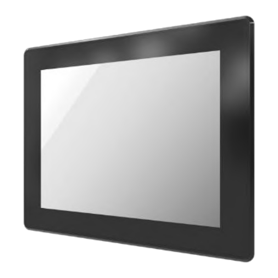
VIO-200/MX200 1.1 Overview The VIO-200/MX200 series touch monitor provide a wide selection of display sizes are available from 12.1” to 21.5” with a format aspect of 4:3 and 16:9, and selected touch type. Featuring with flat surface, IP 65 dust/waterproof front panel, and aluminum die-casting front frame with rugged body structure, it is rugged and reliable for industrial environment. -
Page 11: Vio-212/Mx200
l User’s Manual Chapter 1: Product Introductions VIO-200/MX200 1.1.1 VIO-212/MX200 Key Features • 12.1” TFT XGA 4:3 LCD with Resistive 5-wire / Projected Capacitive Touch • 1x VGA, 1x HDMI, 1x DisplayPort, 1x USB 2.0, 1x COM, 1x Audio • 9 to 48VDC wide range power input •... -
Page 12: Vio-215/Mx200
l User’s Manual Chapter 1: Product Introductions VIO-200/MX200 1.1.2 VIO-215/MX200 Key Features • 15” TFT XGA 4:3 LCD with Resistive 5-wire / Projected Capacitive Touch • 1x VGA, 1x HDMI, 1x DisplayPort, 1x USB 2.0, 1x COM, 1x Audio • 9 to 48VDC wide range power input •... -
Page 13: Vio-W215/Mx200
l User’s Manual Chapter 1: Product Introductions VIO-200/MX200 1.1.3 VIO-W215/MX200 Key Features • 15.6” Full HD 16:9 LCD with Resistive 5-wire / Projected Capacitive Touch • 1x VGA, 1x HDMI, 1x DisplayPort, 1x USB 2.0, 1x COM, 1x Audio • 9 to 48VDC wide range power input •... -
Page 14: Vio-217/Mx200
l User’s Manual Chapter 1: Product Introductions VIO-200/MX200 1.1.4 VIO-217/MX200 Key Features • 17” TFT SXGA 4:3 LCD with Resistive 5-wire / Projected Capacitive Touch • 1x VGA, 1x HDMI, 1x DisplayPort, 1x USB 2.0, 1x COM, 1x Audio • 9 to 48VDC wide range power input •... -
Page 15: Vio-219/Mx200
l User’s Manual Chapter 1: Product Introductions VIO-200/MX200 1.1.5 VIO-219/MX200 Key Features • 19” TFT SXGA 4:3 LCD with Resistive 5-wire / Projected Capacitive Touch • 1x VGA, 1x HDMI, 1x DisplayPort, 1x USB 2.0, 1x COM, 1x Audio • 9 to 48VDC wide range power input •... -
Page 16: Vio-W221/Mx200
l User’s Manual Chapter 1: Product Introductions VIO-200/MX200 1.1.6 VIO-W221/MX200 Key Features • 21.5” TFT FHD 16:9 LCD with Resistive 5-wire / Projected Capacitive Touch • 1x VGA, 1x HDMI, 1x DisplayPort, 1x USB 2.0, 1x COM, 1x Audio • 9 to 48VDC wide range power input •... -
Page 17: System I/O
l User’s Manual Chapter 1: Product Introductions VIO-200/MX200 1.2 System I/O 1.2.1 Rear DC IN COM Port for Touch Panel Connector (Resistive Used to plug a DC power input Touch Only) with terminal block. Use the rear panel female DB-9 touch panel connector to connect the monitor to the system HDMI interface. -
Page 18: Mechanical Dimension
l User’s Manual Chapter 1: Product Introductions VIO-200/MX200 1.3 Mechanical Dimensions 1.3.1 VIO-212/MX200 Unit: mm 1.3.2 VIO-215/MX200 Unit: mm... -
Page 19: Vio-W215/Mx200
l User’s Manual Chapter 1: Product Introductions VIO-200/MX200 1.3.3 VIO-W215/MX200 Unit: mm 1.3.4 VIO-217/MX200 Unit: mm... -
Page 20: Vio-219/Mx200
l User’s Manual Chapter 1: Product Introductions VIO-200/MX200 1.3.5 VIO-219/MX200 Unit: mm 1.3.6 VIO-W221/MX200 Unit: mm... -
Page 21: Chapter 2 Switches And Connectors
Chapter 2 Switches and Connectors... -
Page 22: Switch And Connector Locations
l User’s Manual Chapter 2: Switches and Connectors VIO-200/MX200 2.1 Switch and Connector Locations 2.1.1 Top View AUDIO_IN1 DC_IN1 DP_IN1 HDMI1 VGA_IN1 COM_IN1 USB_IN1 2.1.2 Bottom View SIG_OUT1 2.1.3 Rear I/O... -
Page 23: Connector / Switch Definition
l User’s Manual Chapter 2: Switches and Connectors VIO-200/MX200 2.2 Connector / Switch Definition List of Connector / Switch Connector Location Definition DC_IN1 3-pin DC 9~48V Power Input Connector DP_IN1 DisplayPort Input Connector HDMI HDMI signal connector VGA_IN1 VGA Input Connector COM_IN1 COM Port Input Connector USB_IN1... -
Page 24: I/O Interface Descriptions
l User’s Manual Chapter 2: Switches and Connectors Chapter 2: Switches and Connectors VIO-200/MX200 2.3 I/O Interface Descriptions 2.3.1 Power Connector DC_IN1 Signal 9_48VSB_IN 9_32VSB_ACC GND_VIN 2.3.2 DisplayPort Input DP_IN1 Signal Signal DP_RX3N DP_RX0P DP_RX3P DP_RX2N DP_AUXP DP_RX2P DP_DET DP_RX1N DP_AUXN DP_HPD DP_RX1P... -
Page 25: Hdmi Signal Connector
l User’s Manual Chapter 2: Switches and Connectors Chapter 2: Switches and Connectors VIO-200/MX200 2.3 I/O Interface Descriptions 2.3.3 HDMI signal connector HDMI1 Signal Signal HDMI_RX32+ HDMI_DET HDMI_RX3C- HDMI_RX32- HDMI_RX31+ HDMI_SCL HDMI_RX31- HDMI_SDA HDMI_RX30+ HDMI_5V HDMI_RX3C+ HDMI_HPD HDMI_RX3C+... -
Page 26: Vga Input
l User’s Manual Chapter 2: Switches and Connectors Chapter 2: Switches and Connectors VIO-200/MX200 2.3 I/O Interface Descriptions 2.3.4 VGA Input VGA_IN1 Signal Signal RED+ GREEN+ BLUE+ DDC_SDA_VGA HSYNC VGA_DET VSYNC RED- DDC_SCL_VGA GREEN- BLUE-... -
Page 27: Com Port Input
l User’s Manual Chapter 2: Switches and Connectors Chapter 2: Switches and Connectors VIO-200/MX200 2.3 I/O Interface Descriptions 2.3.5 COM Port Input COM_IN1 Signal RX_R_2 TX_R_2 2.3.6 USB 2.0 Input Connector USB_IN1 Signal USBN_2 USBP_2... -
Page 28: Audio Input
l User’s Manual Chapter 2: Switches and Connectors Chapter 2: Switches and Connectors VIO-200/MX200 2.3 I/O Interface Descriptions 2.3.7 Audio Input AUDIO_IN1 Signal AGND2 AIN_R AGND2 AGND2 AIN_L... -
Page 29: Vio Display Module Connector
l User’s Manual Chapter 2: Switches and Connectors Chapter 2: Switches and Connectors VIO-200/MX200 2.3 I/O Interface Descriptions 2.3.8 VIO Display Module Connector SIG_OUT1 Signal Signal RXO0+ DDC_SDA_VGA RXO0- DDC_SCL_VGA RXO1+ EDID_0 RXO1- EDID_1 RXO2+ EDID_2 RXO2- EDID_3 RXO3+ HDMI_SDA RXO3- HDMI_SCL RXOC+... - Page 30 l User’s Manual Chapter 2: Switches and Connectors Chapter 2: Switches and Connectors VIO-200/MX200 Signal Signal RXE1+ POWER_KEY_R RXE1- AUTO_KEY_R RXE2+ MENU_KEY_R RXE2- UP_KEY_R RXE3+ DOWN_KEY_R RXE3- RXEC+ BL_ADJ RXEC- BL_EN OUT-R+ OUT-R- LEDB LEDA OUT-L+ OUT-L- V5P0SB V5P0SB V5P0SB V5P0SB V5P0_LED V5P0_LED...
-
Page 31: Chapter 3 Front Panel Controls
Chapter 3 Front Panel Controls... -
Page 32: Users Controls
l User’s Manual Chapter 3: Front Panel Controls VIO-200/MX200 3.1 Users Controls POWER MENU INCREASE DECREASE AUTO 3.1.1 Power button Turns the monitor on or off. 3.1.2 1. Blue indicates power on. 2. Yellow indicates standby mode. 3.1.3 MENU/ Enter button Press to view the OSD menu. -
Page 33: Osd Operation
l User’s Manual Chapter 3: Front Panel Controls VIO-200/MX200 3.2 OSD Operation 3.2.1 Luminance ■ Brightness Adjust the luminance level of the screen. ■ Contrast Adjusts the contrast level of the screen. ■ Gamma This item allows you to on or off the Gamma function. ■... -
Page 34: Picture
l User’s Manual Chapter 3: Front Panel Controls VIO-200/MX200 3.2.2 Picture (VGA input only) ■ Phase Adjust the monitor internal signal phase. ■ Clock Adjust the monitor internal sampling clock rate. ■ H. Position Adjusts the position of the screen image left and right. ■... -
Page 35: Setup
l User’s Manual Chapter 3: Front Panel Controls VIO-200/MX200 3.2.5 Setup ■ Language Selects the language in which the OSD menu is displayed. The factory default is English. ■ Mute Allows the user to turn the Mute On or Off. ■... -
Page 36: Chapter 4 System Setup
Chapter 4 System Setup... -
Page 37: Set Torque Force To 3.5 Kgf-Cm To Execute All The Screwing And Unscrewing
l User’s Manual Chapter 4: System Setup VIO-200/MX200 4.1 Set torque force to 3.5 kgf-cm to execute all the screwing and unscrewing. In order to prevent electric shock or system damage, before removing the chassis cover, must turn off power and disconnect the unit from power source. 4.2 Connecting MX200 monitor module with VIO display module 1. - Page 38 l User’s Manual Chapter 4: System Setup VIO-200/MX200 3. Lock the below 6 screws (M4x5L).
- Page 39 l User’s Manual Appendix – Panel Mount VIO-200/MX200 Mounting Guide Flush Mount / Panel Mount: • Cut hole in the wall w/ dimensions according to the screen size you have purchased. Please refer to the next page for the list of cutout dimensions and max wall depths Max.
- Page 40 l User’s Manual Appendix – Panel Mount VIO-200/MX200 VIO-200 / MX200 Series Model Wall Cut-Out (W x H) Unit: mm Max Wall Thickness (mm) VIO-212/ MX200 310 x 249 VIO-215/ MX200 368 x 292.5 VIO-217 / MX200 400 x 331.5 VIO-219/ MX200 442 x 367 VIO-W215 / MX200...
- Page 41 Copyright 2016 C&T Solution Inc. All Rights Reserved www.candtsolution.com...