Table of Contents
Advertisement
Quick Links
E N G L I S H
Rev 9.0
HV Diagnostics, Inc.
North and South America
271 Rope Mill Pkwy, Ste 2
Woodstock, GA 30188
USA
Tel. +1 (678) 445 2555
Fax +1 (678) 445 2557
www.hvdiagnostics.com
sales@hvdiagnostics.com
HV Diagnostics S.à.r.l.
Africa, Asia, Australia,
Middle East
www.hvdsa.com
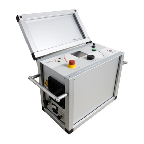
HVA 34
Desc
User Manual
Portable Universal High Voltage
VLF/DC Test Instrument
Advertisement
Table of Contents

Summary of Contents for HV Diagnostics HVA 34
- Page 1 HVA 34 Desc User Manual E N G L I S H Rev 9.0 HV Diagnostics, Inc. North and South America 271 Rope Mill Pkwy, Ste 2 Woodstock, GA 30188 Tel. +1 (678) 445 2555 Fax +1 (678) 445 2557 www.hvdiagnostics.com...
- Page 2 User Manual HV Diagnostics Page 2 Rev 9.0...
-
Page 3: Table Of Contents
Manual Test Mode ..............26 Automatic Test Mode............30 Interrupting a Test ..............37 REPORTING PROCEDURE ........... 38 DISCONNECTION PROCEDURE .......... 43 INSTRUMENT CARE ............. 45 GLOSSARY AND ABBREVIATIONS ........46 DECLARATION OF CONFORMITY ........47 Rev 9.0 Page 3 HV Diagnostics... -
Page 4: Forward
To assure that HVA operators are • general product qualified technicians description. To assure that operators fulfil their • responsibilities Safekeeping NOTICE This manual should always be on hand when using the HVA test instrument HV Diagnostics Page 4 Rev 9.0... -
Page 5: Documentation Conventions
Red outlined circle with red diagonal line: Used to indicate forbidden practices. The described handling practice must not be carried out! Blue circle with white exclamation mark: Used to indicate recommended precautionary measures or a situation that can lead to property damage. Rev 9.0 Page 5 HV Diagnostics... -
Page 6: Legal Considerations
User Manual Legal Considerations Warranty HV Diagnostics provides a one-year warranty from the original purchase date of instrument for all necessary parts and labor. This warranty is void in the event of abuse, incorrect operation or use, unauthorized modification or repairs, or failure to perform the specified maintenance as indicated in this operation manual. -
Page 7: Safety
Earth connections must be made first and removed last! • DUT must be discharged and earthed before disconnecting the test • lead. Avoid testing alone. In the event of an emergency another person’s • presence may be essential. Rev 9.0 Page 7 HV Diagnostics... - Page 8 NOTICE Equipment Handling DUT must have clean connections. Test instruments must only be repaired or modified by authorized HV Diagnostics’ personnel. NOTICE If required according to local safety regulations Wear high voltage gloves when handling high voltage cables and equipment.
-
Page 9: Appropriate Applications
Applied RMS voltage • NOTICE Other Applications Before proceeding, contact HV Diagnostics to validate appropriate use! Operator Qualifications HVA operators must be qualified electrical technicians! Proof of necessary qualifications for working in high voltage domain is mandatory. It is highly recommended that operators have completed an emergency rescue training program. -
Page 10: General Description
Operation Temperature: -5°C to 45° C (23° F to 113° F) Humidity: 5-85% non-condensing Technical Specifications are subject to change. HV Diagnostics reserves the right to modify values in accordance with future development. in combination with locator set (not in scope of supply) -
Page 11: Design Features
100V (AC) Indication To indicate when DUT is not fully Improves safety during Discharge Status • • discharged. normal disconnection Indication LED Red (3) lights when residual procedures voltage greater than 100V Rev 9.0 Page 11 HV Diagnostics... -
Page 12: Materials
Diagnostics. Part. No. Item Description 734 001 HVA34 700 501 HVA 34 HV Test Lead + Alligator Clamps 50kV / 4m 700 505 Grounding Cable Transparent (10 AWG) / 4m (13ft); with 400A alligator clamp Grounding Cable Green 700 048... -
Page 13: Accessories
User Manual Accessories Accessories that are not included with the standard delivery of the HVA and are available for order through HV Diagnostics. Part No. Item Description 700 006 USB Flash Adapter 700 005 Transport Case 700 086 HV Protective Cap... - Page 14 User Manual NOTICE Equipment Not included Cables for remote control and external lamps are not included with the standard issue of the HVA by HV Diagnostics! See options. External Lamp requirements: Rating: Max 1.2 W • Recommended colors: Red, Green •...
-
Page 15: Design And Construction
Test controls and emergency shutdown • HV status information • Left Side Cable and power source connections • External connections • Air Vent • Right Side RS232 port / USB Flash Adapter • Air Vent • Rev 9.0 Page 15 HV Diagnostics... - Page 16 See 5.3 Automatic Test Procedure: Step AR 6 Key switch Locks the unit to prevent against unauthorized use. [on/off] To disable unit Remove key from the OFF Position • To reactivate unit Replace key and turn to ON Position. • HV Diagnostics Page 16 Rev 9.0...
- Page 17 Can be connected to a remote emergency off switch, a gate, foot pedal or dead man switch Air Vent Air inlet with filter, for cooling of electronic elements. Air Vent Air outlet, for cooling of electronic elements. Rev 9.0 Page 17 HV Diagnostics...
-
Page 18: User Interface
Push in / “click” in to enter the new value. Instrument Set-up The HVA instrument settings should be established prior to first utilization and can be modified at any time thereafter. “Instrument Settings” is found in the “Reports & Setup” menu. HV Diagnostics Page 18 Rev 9.0... - Page 19 System Info MAIN Language Instrument Settings “Language” selected here appears as display Set Date and Time hereafter. Reporting: Basic English Startup: Main Menu • Distance Unit: Meter Language: English USB Flash: yes System Info MAIN Rev 9.0 Page 19 HV Diagnostics...
- Page 20 SN: 0123456789012 Version: Installed HVA Firmware • Last Cal. 12/02/2004 SN: HVA unit serial number • Ctrl. 80° F – PU 82° F Last Cal: Date of last calibration • Ctrl.: Temperature • MAIN HV Diagnostics Page 20 Rev 9.0...
-
Page 21: Operation Modes
Suitable for testing extruded cables • (e.g. XLPE cables). Squarewave Not suitable for testing with DC above DUT Vacuum Bottle • Testing voltage rating (X-ray Hazard) Possible in Manual and Automatic test modes • Rev 9.0 Page 21 HV Diagnostics... - Page 22 “Trip out on Arc” mode will immediately switch HV off. Fault detected Burn on Arc Trip Out on Arc Dwell time Starts HV still HV automatically DUT energizes DUT discharges Dwell Time Ends Tripping time recorded Fault conditioned Fault detected HV Diagnostics Page 22 Rev 9.0...
- Page 23 3.0kV Maint. C. HYBR (T) Store Rep. to USB Edit Auto Test Seq. No Reports to Store Start a New Test Instrument Settings Manual Mode Display Contrast Reports & Setup Service 13.3.2009 10:23 MAIN Rev 9.0 Page 23 HV Diagnostics...
-
Page 24: Test Procedure
• Connect the HV cable shield to ground. • Connect other end of HV test lead (clamp including screen protector) • to the DUT. Verify Connections Check that all cables are attached securely. • HV Diagnostics Page 24 Rev 9.0... - Page 25 Select appropriate option from default screen and proceed to appropriate section for further instructions: See 5.2 Manual Test Mode or • See 5.3 Automatic Test Mode Connection Diagram: Sheath/Jacket Test and Sheath Fault Location Rev 9.0 Page 25 HV Diagnostics...
-
Page 26: Manual Test Mode
Mode Waveform • Frequency • Duration • START Timer: 30 m 0s, report active NOTE: If Reporting is active, screen displays additional info. DUT 1.0kV Cable XLPE MAIN SETUP Trip out on Arc HV Diagnostics Page 26 Rev 9.0... - Page 27 Sheath Test Min. = 1 minute; Max. = 15 minutes • Set Duration/Timer Set the test “Trip Current”: 1 min Min. = 0.1 mA, Max. = 5.0 mA • Set Trip Current 5.0 mA CANCEL Rev 9.0 Page 27 HV Diagnostics...
- Page 28 Min. test voltage = 0.0 kV • Max. voltage = 24.0 kV rms (VLF), • 34.0 kV (DC) To accept the value, push in knob (5).The dot in upper right hand disappears indicating that the test voltage is set. HV Diagnostics Page 28 Rev 9.0...
- Page 29 T: 00:03 / 15min MR 6: Manual Mode Finished Display indicates end of Manual Test Manual Mode Test Seq. Test End finished successfully Sine 0.1 Hz Test Voltage: 23.0 kVrms Test Duration: 15 min Rev 9.0 Page 29 HV Diagnostics...
-
Page 30: Automatic Test Mode
Test Voltage: 1.0kVrms Test Voltage: 1.0kVrms Duration 15min Duration 15min Save Sequence Trip out on Arc Trip out on Arc Finished Finished Save or Cancel Save or Cancel CANCEL PREV SAVE CANCEL PREV SAVE HV Diagnostics Page 30 Rev 9.0... - Page 31 (Sinewave or automatically maintains the frequency as close Frequency for Test? Squarewave only) to 0.1 Hz as possible Permitted values: 0.01 - 0.1 Hz in 0.01 Hz 0.1Hz/ Auto • increments CANCEL PREV NEXT Rev 9.0 Page 31 HV Diagnostics...
- Page 32 AS15) Trip out on Arc Finished The sequence is found in the “Edit Auto Test Seq.” Save or Cancel Menu display. See Step AS 1. CANCEL PREV SAVE HV Diagnostics Page 32 Rev 9.0...
- Page 33 Test Voltage: 1.0kVrms Duration: 15 min Wave: Sine 0.1/Auto Trip out on Arc CANCEL SAVE TITLE For naming directions, see 6-Reporting Procedure- Auto Test Seq. Title Report Naming Instructions Edit Title 1.0kV Cable CANCEL SAVE Rev 9.0 Page 33 HV Diagnostics...
- Page 34 Duration: 15 min Waveform: Sine 0.1Hz Trip out on Reporting Active MAIN BACK START Running an Automatic Test - Detailed Steps Steps AR 1-AR 9 describe how to run a test in the Automatic Mode. HV Diagnostics Page 34 Rev 9.0...
- Page 35 “Start Auto Test Seq. “screen will reappear. Auto Test Sine 0.1Hz AR 7: “Startup” appears on the screen to indicate that the HVA is initializing test Test Start up 0.0kV 0.0µA Startup STOP T: 00:00 / 15min Rev 9.0 Page 35 HV Diagnostics...
- Page 36 Display indicates end of Auto Test Auto Test Finished Auto Test. Test End finished successfully Sine 0.1 Hz If reporting is active, the user can immediately Test Voltage: 1.0 kVrms Test Duration:15 min view the report. View the report? HV Diagnostics Page 36 Rev 9.0...
-
Page 37: Interrupting A Test
After test interruption, a message is displayed indicating that the test has been terminated by the user: Manual Mode Finished Manual Mode Test Seq. interrupted by the user at step 1 after 58s Sine 0.1 Hz Test Voltage: 1.0 kVrms Rev 9.0 Page 37 HV Diagnostics... -
Page 38: Reporting Procedure
Reporting is possible in both the test modes. To generate a report in the manual mode, the procedure must begin with “Start a New Test” from the main menu. See 5.2-Manual Test Mode Start a New Test Do you want to store a report? MAIN HV Diagnostics Page 38 Rev 9.0... - Page 39 Sequence” (i.e. steps AS 2, AS 3 and AS 4), these steps are not identical! Steps R 1-R 13 lists the report information that the HVA asks the user to enter when the “Extended” reporting mode is active. Step Procedure (Reporting) Example Rev 9.0 Page 39 HV Diagnostics...
- Page 40 Company Company Name? (Extended only) company HV MAIN PREV NEXT Start New / Report Details R 7: Specify region name DUT: 1.0kV Cable XLPE Region Region Name? (Extended only) region CHEROKEE MAIN PREV NEXT HV Diagnostics Page 40 Rev 9.0...
- Page 41 Steps AR 1-AR 9 - run test MAIN PREV Viewing Report Reports can be viewed directly on the HVA display screen. In “Reports & Setup” the number of reports saved appears in parentheses following Rev 9.0 Page 41 HV Diagnostics...
- Page 42 Load: 57.1nF , 348M Duration: 15min Comp: HV Waveform: Sine 0.1Hz S1: 32,5kV 250µA 0.1Hz Region: CHEROKEE Test Interrupted Station: BETA1 at step 1 after 0min. Oper.: J.SMITH by user stop W.Order: WOO9A MAIN SELECT DEL CLR-ALL HV Diagnostics Page 42 Rev 9.0...
-
Page 43: Disconnection Procedure
Unscrew the test lead from the HV output connector (11) • Disconnect power supply cable from power supply plug (9) Disconnect Ground Disconnect the grounding cable from the HVA grounding connector (10) • Disconnect the grounding cable from the DUT. • Rev 9.0 Page 43 HV Diagnostics... - Page 44 Unscrew the test lead from the HV output connector (11) • Disconnect power supply cable from power supply plug (9) Disconnect Ground Disconnect the grounding cable from the HVA grounding connector • (10) Disconnect the grounding cable from the DUT. • HV Diagnostics Page 44 Rev 9.0...
-
Page 45: Instrument Care
• clean Reinstall the cleaned filter • Replace the protective guard. • If a replacement filter is required, contact HV Diagnostics Storage CAUTION Instrument Damage Do not store the HVA outdoors! Keep the HVA away from liquids! HVA should be stored indoors in the following environmental conditions: Temperature: -25°... -
Page 46: Glossary And Abbreviations
(Infinite current flows in a short circuit) To Trip Opening the circuit (no current flows in open circuit) Very Low Frequency Typically between 0.01 - 0.1 Hz • HV Diagnostics Page 46 Rev 9.0... -
Page 47: Declaration Of Conformity
User Manual Declaration of Conformity The HVA 34 is CE certified and has met the following requirements of the European Council: Category Standard IEC61004-2 , ESD Level 4 (8/15kV) IEC61004-4 , Burst 4kV 5kHz EN55011 Safety EN60950 EN50191 EN61010-1 Rev 9.0... - Page 48 User Manual HV Diagnostics Page 48 Rev 9.0...
Need help?
Do you have a question about the HVA 34 and is the answer not in the manual?
Questions and answers