Table of Contents
Advertisement
Quick Links
Advertisement
Table of Contents

Related Manuals for DRESSER Wayne 700 Series

Summary of Contents for DRESSER Wayne 700 Series
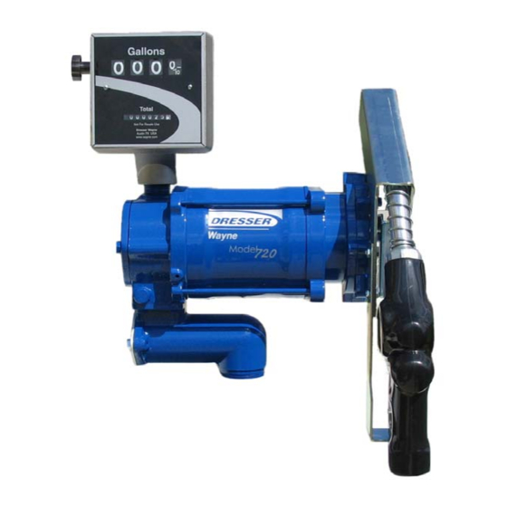
- Page 1 Dresser Wayne 700 Series Small Fleet Pumps...
- Page 2 For product liability to be valid, no changes may be made to the equipment without the written consent of Dresser Wayne. HOW TO CONTACT DRESSER WAYNE ® Trouble with the installation and operation of the pump should be referred to your authorized Wayne service personnel or Wayne Technical Support (1-800-926-3737).
-
Page 3: Table Of Contents
Table of Contents Title Page INTRODUCTION ………………………………………………………………………………………. Equipment Covered …………………….……………………………………………………. Technical Information ………………..……………………………………………………… Local, State, and Federal Codes ..……..……….………………………………………….. Safety Precautions ……………..………….………………………………………………… INSTALLATION ……………………………………………………..………………………………… Equipment Inspection …………………..…………………………………………………… Pump Installation ……………..……………………………………………………………… 2.2.1 Direct Installation on Aboveground Storage Tank ……………..……..………… 2.2.2 Shelf Installation on Aboveground Storage Tank …………..…………………… Electrical Wiring ………….…………………………………..………………………………. - Page 4 Part No. 891817 Rev A February 2007...
-
Page 5: Introduction
INTRODUCTION 1.1. Equipment Covered This manual describes the installation and operation of the Wayne 700 Series Small Fleet Pump & Meter. Any questions concerning the installation and operation of the pump that are not covered in this manual should be referred to your authorized Wayne service personnel or Wayne Technical Support (1-800-926-3737). - Page 6 Nozzle Holder Assembly: Zinc-plated steel. Accommodates standard automatic and manual nozzles. Nozzle can be padlocked to prevent unauthorized use. Mounting Connection: 2” (5 cm) NPT male at base of strainer for tank mounting. Suction Connection: 1” (2.5 cm) NPT female suction tube inlet. Discharge Connection: 1”...
-
Page 7: Local, State, And Federal Codes
1.3. Local, State, and Federal Codes The Wayne 700 Series models are only part of a fuel dispensing system. A fuel dispensing system typically comprises equipment and safety devices from a variety of manufacturers. It is the responsibility of the pump owner to have a qualified installer ensure that all of the... -
Page 8: Safety Precautions
Underwriters Laboratories of Canada Western Fire Chiefs Association 7 Crouse Road 5360 South Workman Mill Road Scarsborough, Ontario, Canada N1R3A9 Whittier, CA 90601 (416) 757-3611 (213) 699-0541 United States Environmental Protection U. S. Department of Labor, Agency Occupational Safety and Health Administration Office of Underground Storage Tanks (OSHA) Washington, DC 20402 401 M St., SW (05-400WF) -
Page 9: Installation
Pump Installation • The Wayne 700 Series is designed for use with aboveground storage tanks. The pump may be mounted directly into a fitting on the top of the tank or on a shelf on the side of the tank. -
Page 10: Shelf Installation On Aboveground Storage Tank
2.2.2. Shelf Installation on Aboveground Storage Tank • The Wayne 700 Series may be mounted on a shelf on the side of the tank to make the user controls more accessible with larger tanks. • The installer must provide the necessary mounting hardware, piping, and safety valves according to the federal, state, and local codes. -
Page 11: Wiring
2.3.4. Wiring • All wiring should be UL-Listed, gasoline- and oil-resistant wire rated at least 90ºC, 600V, Gas & Oil Resistant. • All AC wire terminations should be made in the motor junction box. Make sure all wire connections are tightly spliced and secured with a wire nut. Use electrical tape to close the open end of the wire nut. -
Page 12: Wiring Diagram
2.3.6. Wiring Diagram Handle Pump Motor 115 VAC Ground Screw Junction Box Breakers Notes: All equipment to be installed in accordance with all applicable local, state, and federal codes, including, but not limited to, the National Electrical Code (NFPA 70), NFPA 30, the Automotive and Marine Service Station Code (NFPA 30A), and the Standard for Storage of Flammable and Combustible Liquids at Farms &... -
Page 13: Hose And Accessories Installation
2.4. Hose and Accessories Installation • Hose assemblies should be U.L. Listed and installed in accordance with the manufacturer’s instructions. • Install the hose assembly after the pump is installed. o To ensure a proper joint, wash all cutting oil off the threads and use a U.L. Listed gasoline-resistant pipe joint sealing compound. - Page 14 Part No. 891817 Rev A February 2007...
-
Page 15: Start-Up
All water has been removed from the tank and the tank has a sufficient amount of fuel for testing (above bottom of suction line). NOTE: Do not use the Model 700 Series to remove water from the tank. It will harm the pump. 3.2. -
Page 16: Meter Check (Calibration) - For Units Equipped With A Meter/Register
3.2.4. Meter Check (Calibration) - For Units Equipped with a Meter/Register All meters are tested and calibrated for gasoline at the factory before shipping. As part of the start-up procedure, the meter accuracy should be verified based on the actual product dispensed, added accessories, installation conditions, or any changes that could have occurred during rough transit.. -
Page 17: Operation
OPERATION 4.1. Safety Items You Should Know • Know how to turn OFF power to the pump in an emergency. • Use the pump for appropriate applications. Use only low viscosity petroleum fuels – diesel, including biodiesel blends up to 20%; kerosene; and gasoline with up to 15% ethanol. -
Page 18: Portable Tanks And Containers
4.1.1. Portable Tanks and Containers Portable containers of 12 gallons (45 liters) or less shall not be filled while they are in or on a motor vehicle. Filling portable containers, especially when they are sitting on a non- conductive surface such as a floor mat or a plastic bedliner in the back of a pick-up truck, can present a possible safety hazard and should be avoided as so stated in the following WARNING: WARNING... -
Page 19: Maintenance
MAINTENANCE 5.1. Preventive Maintenance The safety precautions described in Section 1.3 apply to the following preventive maintenance procedures. A correctly installed pump, given proper preventive maintenance attention, will seldom require emergency service. Perform the following checks on a regular basis: •... -
Page 20: How To Get Service On Your Pump
To remove the strainer: • Remove the two bolts and strainer cover. Place a container under the opening to catch the petroleum and sediment. • Pull out the strainer and wash the screen in gasoline. Use compressed air to dislodge lint and other foreign particles. -
Page 21: Troubleshooting
TROUBLESHOOTING 6.1. Troubleshooting Tips SYMPTOM DIAGNOSIS & CORRECTIVE ACTION • Motor does not start or No electrical power to the pump. make any noise. o Check that the breaker is turned on. o Test for adequate voltage in the motor junction box (within 10% of nameplate voltage). - Page 22 SYMPTOM DIAGNOSIS & CORRECTIVE ACTION • Motor stalls when Bypass valve is stuck in closed position. nozzle is closed. o Unscrew the bypass valve cover. Remove the bypass valve and clean or replace as necessary. • Low voltage. o Test for adequate voltage in the motor junction box (within 10% of nameplate voltage).
- Page 23 If so, clean or replace the vacuum breaker. o Note: On other 700 Series models without the vacuum breaker, it is possible to siphon product through the pump. February 2007...
- Page 24 Part No. 891817 Rev A February 2007...
- Page 25 The contents should not be construed as a commitment by Dresser, Inc. who assumes no responsibility or liability for inaccuracies that may appear in this publication. Dresser Wayne, Dresser, Inc., is located at 3814 Jarrett Way, Austin TX 78728. Wayne’s general telephone number is (512) 388-8311.
- Page 26 Wayne Division, Dresser, Inc. 3814 Jarrett Way, Austin, TX 78728 (512) 388-8311 Part No. 891817 Rev A ©2007 Dresser, Inc. February/07 Part No. xxxxxx Rev A February 2007...
Need help?
Do you have a question about the 700 Series and is the answer not in the manual?
Questions and answers