
Summary of Contents for PI Micos WT-120
- Page 1 User Manual WT-120 Goniometer 1 WT-120 Goniometer 6560-9- Order no. Order no. 6560-9- DC-B-082 2Phase-070 User Manual Version: 00.000 Date: 10.08.2016 without AE-060 AE-060, angular scale...
- Page 2 2 WT-120 Goniometer © 2015 PI miCos GmbH, Eschbach, Germany. The text, photographs and drawings in this manual are protected by copyright. With regard thereto, PI miCos GmbH retains all rights. The use of any text, images and drawings is permitted only in part and only when indicating the source.
-
Page 3: Table Of Contents
WT-120 Goniometer 3 CONTENTS Technical Features ABOUT THIS DOCUMENT 4.7.1 Load Capacity Data Objective and Target Group of this User Manual 4.7.2 Motors Symbols and Typographic Conventions 4.7.3 Measuring System Other Applicable Documents 4.7.4 Limit Switch SAFETY 4.7.5 Connector 4.7.6 Technical Data... -
Page 4: About This Document
• Basic knowledge on servo systems, motion control concepts and The WT-120 is a laboratory device as defined by DIN EN 61010. It is applicable safety measures is assumed. intended for indoor use and use in an environment that is free of dirt, oil, •... -
Page 5: General Safety Instructions
E-120. 2.2.2 Measures during Installation 1. Only use the WT-120 for its intended purpose, and only use it if it is in The WT-120 may be damaged by excessively long screws and wrongly good working order. -
Page 6: Measures During Start-Up
Set the control signal so that the moving part does not stop abruptly or try to continue motion at the end of the travel range. Do not put your WT-120 into operation until it is fully mounted and connected. ... -
Page 7: Unpacking
AE-060 AE-060, angular scale NOTICE All specifications in this user manual refer only to the standard products that are included in the PI miCos Product View catalog. Any special features that are different, in particular special requests... -
Page 8: Safety Instructions
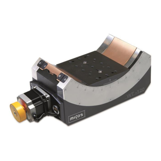
8 WT-120 Goniometer Safety Instructions Scope of Delivery • Goniometer according to order. • Mounting accessories (screws & pins) in fast-sealing bag. Optional Accessories Obtain more information on optional accessories from our customer service department (chapter 9). Technical Features 4.7.1 Load Capacity Data... - Page 9 WT-120 Goniometer 9 4.7.2 Motors DC-B-082 Motor type DC brush RE-040 Nominal voltage Max. continuous current 3.12 Electrical resistance 1.16 Electrical inductance 0.329 Torque constant mNm/A 60.3 Velocity constant rpm/V n/M slope curve rpm/mNm 3.04 no load velocity at 48 V...
- Page 10 10 WT-120 Goniometer 4.7.3 Measuring System 4.7.4 Limit Switch AE-060 WT-120 Mechanical limit switches Angular optical encoder RS-422 quadrature Encoder type Angular incremental RGH-24 Max. voltage (resistive load) Quadrature counts per 360° 4140619 Max. current (resistive load) Resolution 8.694352221e-5 Contact type...
-
Page 11: Connector
WT-120 Goniometer 11 4.7.5 Connector ST-050 DC motor, HD Sub-D (m), 15-pin assignment with mechanical switches Limit forward HD Sub-D (m), 15-pin Function Limit reverse Encoder channel A+ LCOM Limit common Encoder channel B+ Encoder channel I+ EGND Supply encoder GND... -
Page 12: Technical Data
12 WT-120 Goniometer 4.7.6 Technical Data TECHNICAL DATA Travel range (°) Wobble (bearings) (µrad) ± 125 Weight (kg) 11.5 Motor DC-B-082 2Phase-070 Linear scale AE-060 Max. velocity (°/sec) Calculated resolution (°) 0.0001 (RE) 0.01(FS) 8.7E-05 Typical resolution (°) 0.004 0.004 0.001... -
Page 13: Ambient Conditions
Ambient Conditions Mounting the goniometer For indoor use only. Requirements • The WT-120 was calibrated at an ambient temperature of 20 °C (+/- 3 You have read and understood the general notes on installation (see °C). chapter 5.1). • The permissible operating temperature is between 20 °C and 40 °C. -
Page 14: Mounting The Load
14 WT-120 Goniometer Mounting the WT-120 Mounting the Load 1. Move the motion platform of the WT-120 to the center position by hand until all of the countersunk holes in the base body required for mounting Requirements are accessible (see following illustration). -
Page 15: Mounting With
General Notes on Start-Up This goniometer must be started up with a suitable cable and the associated controllers. MAINTENANCE Depending on the operating conditions and the period of use of the WT-120, the following maintenance measures are required: Maintenance Run •... -
Page 16: Troubleshooting
If you have questions concerning your system, have the following charge. information ready: Any old PI miCos equipment can be sent free of charge to the following 1. Product codes and serial numbers of all products in the system address: 2. -
Page 17: Eu Declaration Of Conformity
WT-120 Goniometer 17 11. EU Declaration of Conformity An EU Declaration of Conformity has been issued for the WT-120 in accordance with the following European directives: 2014/30/EU, EMC Directive 2011/65/EU, RoHS Directive The applied standards certifying the conformity are listed below.
Need help?
Do you have a question about the WT-120 and is the answer not in the manual?
Questions and answers