
Related Manuals for Muncie OMNI-SYSTEM PLUS

Summary of Contents for Muncie OMNI-SYSTEM PLUS
- Page 1 OMNI-SYSTEM PLUS S N O W & I C E D I V I S I O N OPERATION AND CONFIGURATION MANUAL...
- Page 2 PAGE 1 OMNI-SYSTEM...
-
Page 3: Table Of Contents
TABLE OF CONTENTS Controller Specifications and Features..................4 Controller Navigation/Button Assignments ................5 Body Selection and Diagnostics Connection ................6 Main Operating Screen—Standard Spreader Body..............7 Main Operating Screen—Anti-ice/Tow Plow ................8 Main Operating Screen—Directional Body/Sprayer ..............9 Main Operating Screen—External Equipment Body/Uncontrolled Body .......10 Operator Adjustments/Datalogging Screens ................11 Accessing and Navigating Configuration Menu/Firmware Updates ........12 System Profiles..........................13 Wi-Fi configuration ........................14... - Page 4 PAGE 3 OMNI-SYSTEM...
-
Page 5: Controller Specifications And Features
FEATURES & SPECIFICATIONS Controller Specifications • Color Touchscreen Display • Uses LED Back Lighting • Tactile Switch Controls • Built-in Audible Alarm • Ergonomic Control Design • GPS based Data-Logging • Wi-Fi Connectivity • CANBUS Platform • Air & Road Temperature Sensor Ready Controller Features •... -
Page 6: Controller Navigation/Button Assignments
CONTROLLER OPERATION CONTROLLER NAVIGATION: BUTTON ASSIGNMENTS: Cycle Screens: Depress the Auger or Spinner Spreader: Press to initiate the spreader system. to cycle screens. Blast: Press to “Blast” or increase the granular rate to a Adjustments: Tap the appropriate touch screen configurable set point for an adjustable time. -
Page 7: Body Selection And Diagnostics Connection
Diagnostic Connection – This feature allows the user to connect to Muncie for diagnostic purposes. Simply connect to a Wi-Fi network and press the Start button to connect to Muncie for Diagnostic help. Remote Connection Status – Displays the current state of the wireless connectivity (Muncie Use Only). -
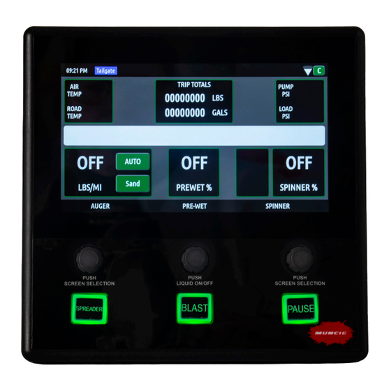
Page 8: Main Operating Screen-Standard Spreader Body
CONTROLLER OPERATION Main Operating Screen – Standard Spreader Body: Air Temp/Road Temp – Displays air and road temperatures. Temperatures will only Body Joystick System Wi-Fi Time Vehicle Type Pressure/ display if IR temperature sensor is installed. Speed Temps Trip Totals – Displays the material and liquid totals per trip. -
Page 9: Main Operating Screen-Anti-Ice/Tow Plow
MAIN OPERATING SCREENS Main Operating Screen – Anti Ice: Liquid Spreader Wi-Fi Joystick Rate Mode Air Temp/Road Temp – Displays air and road Mode Not temperatures. Temperatures will only display if IR Shown temperature sensor is installed. Joystick Mode – Displays the current piece of equipment the joystick is controlling. -
Page 10: Main Operating Screen-Directional Body/Sprayer
MAIN OPERATING SCREENS System Mode Body Joystick Main Operating Screen – Pressure/ Type Mode Oil Temps Directional Body: Not Shown Air Temp/Road Temp – Displays air and road temperatures. Temperatures will only display if IR temperature sensor is installed. Trip Totals – Displays the material and liquid totals per trip. -
Page 11: Main Operating Screen-External Equipment Body/Uncontrolled Body
MAIN OPERATING SCREENS Main Operating Screen – External Equipment Body: Air Temp/Road Temp – Displays air and road temperatures. Temperatures will only display if IR temperature sensor is installed. Trip Totals – Unused for this mode. The system is simply turning flow on and off to designated output. System Pressures/Oil Temperature –... -
Page 12: Operator Adjustments/Datalogging Screens
Diagnostic Connection – This feature allows the user to pre-configured body modes. Additional body connect to Muncie for diagnostic purposes. Simply connect configurations can be added by contacting the to a Wi-Fi network and press the Start button to connect to Muncie Power Products Snow and Ice Team. -
Page 13: Accessing And Navigating Configuration Menu/Firmware Updates
System Sync: In the event a new module is replaced in the system, press the “system sync” button to manually resend the appropriate settings to the new module. System Versions: Displays the current version of firmware installed on the system (Muncie Use Only). PAGE 12 SNOW & ICE DIVISION... -
Page 14: System Profiles
CONFIGURATION MENU Configuration Menu – System Profile: Truck Profile Number – The profile contains all of the unique calibration settings, button mapping, and I/O configurations of the system. The user is able to download this file (system profile) and load to identical systems within a fleet to mirror settings. -
Page 15: Wi-Fi Configuration
CONFIGURATION MENU Configuration Menu – Connecting to Wi-Fi: View Networks/View Config – Toggle this button to switch between connected Wi-Fi networks vs. available networks. Available Networks – To connect to an available network, click on the view networks button and select the preferred Wi-Fi network and enter the appropriate credentials. -
Page 16: Datalogging Setup
CONFIGURATION MENU Configuration Menu – Datalogging: Flash Drive Status – Displays the status of the flash drive. To connect, simply insert a USB flash drive in the USB port. The flash drive should auto connect. If not, press the “Connect USB” button. To disconnect, press “Disconnect USB button. - Page 17 CONFIGURATION MENU Global Equipment Settings: Pump Type – Toggle the pump type button to select gear, piston, or disabled. Disabled is utilized for piston pumps, but the valve network is not equipped with an electrically controlled main relief. Main Relief Press – Select to adjust the Main Relief Pressure.
- Page 18 CONFIGURATION MENU Global Equipment Settings: Air/Road Temp – This text displays the current state temperature being reported from the air/road temp sensor. Road Temp Offset – This adjustment allows the road temperature to be tuned if the current reading is slightly inaccurate. 1.
-
Page 19: Global Spreader Settings
CONFIGURATION MENU Global Equipment Settings: Retain Settings – The retain settings button allows the system to retain the Auger, Liquid, and Spinner rates through power cycles. Caution: This will cause the spreader controller to retain the settings after the controller has been powered off. -
Page 20: Granular Rate/Liquid Rate Setpoints
CONFIGURATION MENU Granular Setpoints: Granular Mode – Two operating modes are available: Setpoint – If “Setpoint Mode” is selected, the user has the ability to dial in the exact auto mode settings available to the operator. Up to six rates are available to pre-configure. Range –... -
Page 21: Configuration Per Body Selection
These body types are configured by a Muncie Technician before the system is shipped. If an alternate body type is needed please contact Muncie Power Products to have it added to the system profile. Standard Body Settings: Current Body – This setting indicates the pre- configured body types available. - Page 22 CONFIGURATION MENU Auger Calibration Process: Purpose – The spreader calibration is recommended for auto mode accuracy. It allows the controller to accurately discharge material at the rate shown and accurately log how much material is discharged. 1. Load the spreader with the primary material and weigh the truck.
- Page 23 CONFIGURATION MENU Pre-Wet Calibration Process: Pre-Wet Cal – Performing a pre-wet calibration increases the accuracy of the pre-wet output. 1. Place a 5 gallon bucket or other know volume container under the pre-wet nozzle. 2. Press the “Calibrate Button” to initiate the process.
- Page 24 CONFIGURATION MENU Directional Bodies: Auger Flow – Select the Auger Flow “Min/Max” button to adjust the speeds. The Min setting needs to be adjusted so that the auger is barely turning at this setpoint. The Max setting is the maximum preferred auger speed.
- Page 25 CONFIGURATION MENU Tow Plow: Auger Flow – Select the Auger Flow “Min/Max” button to adjust the speeds. The Min setting needs to be adjusted so that the auger is barely turning at this setpoint. The Max setting is the maximum preferred auger speed.
- Page 26 External Bodies. This body type is designed to send a fixed amount of flow to an external source for use with auxiliary motor/cylinder functions not controlled by the OMNI-System Plus. Next toggle the up and down button to adjust the settings. Uncontrolled Body: This body does not have a configuration page.
-
Page 27: Cylinder Configurations (Plow And Hoist)
CONFIGURATION MENU Plow Body: Plow Down Float – This setting allows the plow float and power float to be enabled or disabled. Plow Down Cylinder – This setting determines the cylinder type. Plow Down Float Press – Adjust this setting when the system is equipped with power float. - Page 28 CONFIGURATION MENU Dump Settings: Dump Cylinder – This setting determines the cylinder type. Dump Relief – Adjust this setting to control the downside relief pressure. Keep in mind that the downside relief is disabled when the cylinder is set for single acting. Dump Up Speed –...
-
Page 29: System Alerts
Error transferring file to USB drive Speedometer signal not found, system will use GPS Switched to GPS Groundspeed groundspeed until resolved Hidden until unit configured and connected to Muncie AVL System Fault OMNI-System Plus PAGE 28 SNOW & ICE DIVISION... -
Page 30: Notes
NOTES PAGE 29 OMNI-SYSTEM... - Page 31 NOTES PAGE 30 SNOW & ICE DIVISION...
- Page 32 201 East Jackson Street • Muncie, Indiana 47305 800-367-7867 • Fax 765-284-6991 • info@munciepower.com • www.munciepower.com Specifications are subject to change without notice. Visit www.munciepower.com for warranties and literature. All rights reserved. © Muncie Power Products, Inc. (2018) A Member of the Interpump Group IN20-03 (Rev. 05-20)
Need help?
Do you have a question about the OMNI-SYSTEM PLUS and is the answer not in the manual?
Questions and answers