Table of Contents
Advertisement
Quick Links
Advertisement
Table of Contents

Summary of Contents for Newport OPHIR EA-1
- Page 1 EA-1 ETHERNET ADAPTER USER MANUAL OPHIR OPTRONICS www.ophiropt.com/photonics...
-
Page 2: Table Of Contents
Contents About this document: ............................... 4 Definition of Terms: ..............................4 Chapter 1 - Introduction: ..............................5 General Description: ..............................5 Package Contents: ................................. 6 Connection Protocols: ..............................6 Ground Connections to EA-1 Device: ..........................7 Chapter 2 - Configuration: ..............................8 Device Default Configuration: ............................ - Page 3 Using HTTP Protocol: ..............................28 Searching for EA-1 Devices on the Network: ......................28 Summary of TCP Port Numbers: ..........................29 Chapter 6 - Details of User Commands: .......................... 30 General Rules: ................................30 Special Rules When Using Telnet: ..........................30 UDP Protocol: ................................
-
Page 4: About This Document
About this document: This manual contains instructions for using the Ophir “EA-1 Ethernet Adapter” device. The manual is divided into several sections: Introduction to the EA-1 and general description of the product Instructions for initial configuration and setup ... -
Page 5: Chapter 1 - Introduction
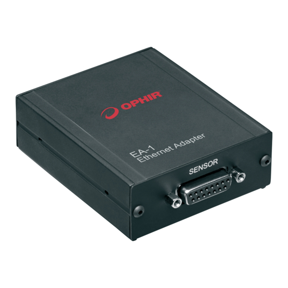
Chapter 1 - Introduction: This chapter provides some basic information about the EA-1 and a general description of the device. General Description: The EA-1 is an Ethernet Adapter intended for OEM customers. It is designed to work with standard or OEM Ophir smart-plug sensors using a D15 connector. -
Page 6: Package Contents
On the sides: Two M3 mounting holes are provided along each side of the device allowing attachment of an optional bracket (as shown in the illustration above). The bracket makes it easier for the customer to attach the device into his mechanical system. A set of two brackets and four screws are supplied with the device. Full device specifications are included in Appendix A below. -
Page 7: Ground Connections To Ea-1 Device
several buttons that allow entry into several lower level pages. In addition, there is an option to send software commands directly using the HTTP protocol. As for the Telnet connection, the host device is the “client” and the EA-1 device is the “server”. Details are listed later on in this document. UDP: For situations where Telnet is not available (for example - working with some PLCs) another option is to connect to the device using a UDP connection. -
Page 8: Chapter 2 - Configuration
Chapter 2 - Configuration: Configuration of the EA-1 adapter is necessary before using the device for the first time. In particular, the IP address (and other related settings) must be set. Two IP address modes are supported - static allocation (default) or dynamic allocation (using DHCP). - Page 9 An IP address for the EA-1 adapter needs to be obtained from the network administrator; this example uses an IP Address 172.16.16.49, Subnet Mask 255.255.255.0 (default), IP Gateway 172.16.16.1 Note: In order to connect to the device using a PC, it may be necessary to first set the PC to a static IP address. Instructions for doing this are shown in Appendix 2 below.
-
Page 10: Setting Up A Static Ip Address Using Telnet
Enter the new IP address, and click on “Save”. The following message will be displayed at the bottom of the webpage: The settings have been saved in the device EEPROM but will only become active after the next power up of the device. - Page 11 Check the “Telnet Client” option is switched on, then click “OK” and close the window. To open the Telnet connection, go to a command prompt window. Go to the “Start” button, click in the “Search programs and files” box, and type “cmd”, then <enter>: Alternatively, open windows explorer and navigate to the folder “C:\windows\system32\cmd.exe”...
-
Page 12: Setting Up A Static Ip Address Using The Usb Virtual Com Port
$VE <enter> queries the firmware version to check the connection, response should be “*EA1.06” [the actual version will vary according to released firmware version] $NS 1 <enter> queries the present setting of IP address in the local EEPROM $NS 1 172.16.16.49 <enter> writes the new IP address into the local EEPROM, response should be “SAVED (need reset)”... -
Page 13: Changing To Dynamic Ip Address Allocation Mode
Note: If the user changes the IP address to a new setting and presses “Save”, the new value will be saved to local memory inside the device and will be used the next time the device powers up. However, if the user then tries to restore the value back to its original setting and then presses “Save” again before exiting the application and resetting the device, a message “Unchanged”... -
Page 14: Setting The User Device Name
This app also includes an automatic search feature which locates all Ophir devices on the network. This is a convenient method to use if the present IP Address is not known before trying to set the dynamic mode. When using this software, the EA-1 device can be accessed via Ethernet or via USB VCP. -
Page 15: Returning To Factory Default Settings
Returning to Factory Default Settings: If connection has been lost to the device, and there is no way to find out the present IP address setting, as a last resort the user can return the device temporarily to factory default settings in order to establish a connection and then update the configuration as required. -
Page 16: Chapter 3 - Http And The Built-In Web Server
Chapter 3 - HTTP and the Built-In Web Server: The EA-1 Adapter has a web server built into its firmware, allowing the user to perform simple tasks via a standard web browser such as Internet Explorer. Tasks that can be performed via the web server include: ... - Page 17 Click on the “Command” window, and type the command including the leading “$” symbol. For example, type “$VE” and then press <enter>. The response will appear below the window in red, for example “*EA1.03”. A full list of user commands is included at the end of this manual. To view the power being measured by the attached sensor, return to the “Start Page”...
-
Page 18: Chapter 4 - Using The "Ophirethernetapp" Application
Open the application by clicking on the shortcut or direct on the EXE file. The following window will appear: On opening the application, or after clicking on “Search Sensors”, the application searches for all Ophir EA-1 Adapters it can locate on the network and lists them in the box shown above, with details of the sensor attached to... -
Page 19: The Main Sensor Window
each device. While performing the search, the mouse icon is changed to the “busy” symbol. The search includes devices it can locate either via Ethernet or via the USB Virtual COM Port connection, if present. The main sensor window: Click on one of the sensors shown in the list to highlight it and click on the “Start Selected” button (or click on “Start All Found”... -
Page 20: Choosing Measurement Range
Choosing Measurement Range: Choose the power or energy range using the drop down “Range” menu as shown: In most cases, an AUTO range option is available, allowing the sensor to choose its own best measurement range based on the present power incident on sensor. Alternatively the customer can choose manually from the available ranges, shown in descending order. -
Page 21: Saving The Startup Settings
If less than six favorite wavelengths are currently defined, the user can simply choose “add” and then define a new measurement wavelength directly: Use the scroll bar to increase of decrease the chosen wavelength, or simply type the value in the window, for example 567 as in the example above. -
Page 22: Sending User Commands
Sending User Commands: In order to send a user command, clock in the “Send Command” window, type the command and click on “Send”. The response will appear to the right of the “Send” button. In this case, it is not necessary to add the “$” symbol in front of each command, as it is added automatically by the application: A detailed list of user commands is added below. -
Page 23: Configuration And Setup
The controls in the energy screen are similar to the power screen, except that the statistics are not available. In addition there is a status label just below the Energy value display, as shown below: Wait for the “READY” status before trying to measure a pulse of laser on the sensor. If the measurement displays “OVER”... -
Page 24: Firmware Upgrade
The Local IP, Subnet Mask and Default Gateway can be adjusted as described in the Configuration section - any changes will be saved in the local EEPROM of the device and will take effect after the next startup. DHCP mode (“Dynamic Host Configuration Protocol”, dynamic allocation of the IP address) can be enabled or disabled using this setup screen. -
Page 25: Zeroing
The location of firmware files is under the application installation folder, usually: C:\Program Files\Ophir Optronics\Ophir Ethernet Application\Firmware\ or: C:\Program Files (x86)\Ophir Optronics\Ophir Ethernet Application\Firmware\ Note: It is recommended not to upgrade firmware unless a new version is actually available. If a firmware upgrade is not actually required, the following message will be displayed; answer “no” to abort the firmware upgrade: In the event that a new firmware upgrade is available and necessary, the software will continue with the upgrade automatically. -
Page 26: Help Menu
Zeroing should be performed with no laser light on the sensor, and with the sensor covered and protected from any sources of heat or light. At the end of the zeroing, press the “Save” button to store the new zero values in the local EEPROM. - Page 27 The log file contains the following information: Line 1: EA-1 device user-name, sensor name, sensor S/N, IP address Line 2: Date and start time of the log Line 3: Column headers: Time(s) Value Unit Line 4+: logged data: time-stamp (in seconds from the start of log), value in scientific format, measurement units Note: In some European countries the default separator character is a comma “,”...
-
Page 28: Chapter 5 - Other Features And Protocols
Chapter 5 - Other Features and Protocols: This chapter contains some general information about connecting with the EA-1 device using other methods and querying Ophir devices on the network using the UDP Protocol. Using HTTP Protocol: Using an HTTP connection, commands can be sent directly to the device using the IP address and some extra characters. -
Page 29: Summary Of Tcp Port Numbers
In addition, UDP can be used to send commands and receive replies, as an alternative to Telnet. See details below in chapter “Details of User Commands”. Summary of TCP Port Numbers: By convention TCP uses the following port numbers: Connection: Port Number: Telnet HTTP... -
Page 30: Chapter 6 - Details Of User Commands
Chapter 6 - Details of User Commands: The intended use of the EA-1 Adapter is primarily for OEM customers who wish to embed the device inside their own laser system. In order to allow customers to control the device using their own software package, a set of “User Commands”... -
Page 31: Ethernet Commands
Send a UDP packet to device IP address port 11000 with the command string as defined here: Command String Format: OPHCMDXXXX$VE<params>[CR] where: OPHCMD = a special 6 letter prefix we have defined for UDP commands. XXXX = a user defined 4-character string (ASCII characters), a code defined by the user, which will be returned by the EA-1 in the response to this command. - Page 32 Queries (with no parameter) or sets “Device User Name”. If present value is undefined, returns “?NOT DEFINED”. If parameter is “DELETE”, the present value is erased. Note: “DELETE” must be written in upper case letters only. Examples: “$DN WELDING MACHINE” -> saves the user name “WELDING MACHINE”, and returns “*OK” “$DN”...
-
Page 33: General Notes On Commands
Network Dynamic IP Address Mode ($ND): This command sets, or queries the present setting, of DHCP (Dynamic IP address mode). Any changes will be used after the next device power up. Parameters: No parameter -> queries present setting, replies 0 (DHCP OFF) or 1 (DHCP ON) 0 ->... -
Page 34: General Commands
Note: Some of the commands are specific to the type of sensor being used, for example some commands work only for energy mode; other commands work only with sensors which have a continuous calibration curve (all photodiodes and some thermopiles) rather than discrete calibration points (some thermos). Some commands work only with thermopile or only with photodiode sensors. -
Page 35: Zeroing Commands
Sensor Information ($HI): $HI[CR] -> * <2 letter sensor code> <S/N of sensor> <name of sensor> <capability code>[CR][LF] Returns information on the sensor, including name and S/N. The 2 letter code is “TH” for thermopile sensors, or “SI” for photodiode sensors. Other Ophir sensors have different codes, but are not currently supported by the device. - Page 36 All Ranges ($AR): $AR[CR] –> * 2 AUTO 10.0W 3.00W 300mW 30.0mW [CR][LF] {Returns a list of all available power ranges (scales) (or energy scales if sensor is set to measure energy) including an index value showing which range is presently selected. In the example shown above, top scale (index 0) is 10W, scale 1=3W, scale 2=300mW, scale 3=30mW, and an auto- ranging scale is also available ("AUTO"...
-
Page 37: Energy Measurement Commands (Thermopile Sensors)
Energy Measurement Commands (Thermopile Sensors): This section is relevant for thermopile sensors measuring single-shot energy pulses. Some of the commands are relevant also for pyroelectric/PD-C sensors measuring pulsed laser pulses, as will be noted below in a separate section. Force Energy Command ($FE): $FE[CR] ->... -
Page 38: Wavelength Commands
1= set low threshold (default / 3) 2= set medium threshold (default) 3= set high threshold (default x 3) NOTES ON MEASURING ENERGY IN SUPPORT SOFTWARE: Assuming that the support software is started after the device has been powered up, the correct sequence for working is as follows: Set the unit to the lowest energy range that will not result in over-range message. - Page 39 Example 1: "Discrete" laser wavelength points (some thermopile sensors) "* DISCRETE 2 CO2 YAG [CR][LF]" Where: "DISCRETE" indicates that this sensor contains several discrete laser wavelength calibration points, rather than a sensitivity curve. These points are hard wired inside the sensor and cannot be changed by the user, but the user has the option to choose between the individual points thereby adjusting the sensor's sensitivity according to the laser being used.
-
Page 40: Continuous Send Commands
“?BAD WL” if wavelength value entered is out of range of defined curve. “?BAD PARAM” if parameter is out of range} Examples: Assume $AW command returned: "* CONTINUOUS 200 3000 2 2490 971 532 NONE NONE NONE[CR]" $WD 7 1111 -> ?INDEX NOT IN RANGE[CR][LF] $WD 5 111111 ->... -
Page 41: Misc. Commands
replies in the Command/Reply mode, the receive buffer of the PC or host device must be flushed by continuously reading data until there is a "time-out". The time-out should be set short enough to avoid the software needing to wait a long period of time after the data stops arriving. Misc. -
Page 42: Commands For Pyroelectric/Pd-C Sensors
Error 0x0000 1000 Position not measured (sensor can't measure position) Error 0x0000 2000 Signal too low (i.e. signal is just noise, no meaningful measurements) Error 0x0000 4000 Position Measurement out of range (i.e. out of outer circle) Error 0x0000 8000 General Position Measurement Error Size Codes (bits 16 warning, 25-31 error): Warning... -
Page 43: Continuous Send Modes For Pyroelectrics/Pd-C Sensors
User Threshold ($UT): $UT -> 300 106 2500[CR] {This command queries or sets the user threshold for the chosen energy scale in units of 1 in 10,000 of the chosen full scale energy. For example setting the value to 300 will set the User Threshold for the sensor to 3% (= 300/10000) of the chosen energy scale. - Page 44 “2222” is the pulse index as a decimal integer (up to a maximum of 2^32-1) “33333” is the timestamp in microseconds as a decimal integer (up to a maximum of 2^32-1) 1.234E-1 is the energy measured in Joules, 123.4mJ 3. BINARY MODE $CS 4 (max data rate ~40kHz): Using this mode, the maximum data rate of 40kHz can be achieved.
- Page 45 Details of data package format: Byte_0 (status byte) 0x00 = regular energy value 0x01 = energy value OVER (out of range) 0x0A = frequency value Byte_1 Timestamp byte 0 (LSB) Byte_2 Timestamp byte 1 Byte_3 Timestamp byte 2 (MSB) Byte_4 (FLOAT) Value (energy or frequency) byte 0 (Least significant) Byte_5 (FLOAT) Value (energy or frequency) byte 1...
-
Page 46: Appendix 1 - Device Specifications - Ea-1 Ethernet Adapter
Appendix 1 - Device Specifications - EA-1 Ethernet Adapter: Specifications, Thermopile & Photodiode Sensors: Input Ranges 15nA - 1.5mA full scale in 16 ranges A-to-D Sampling rate 15Hz A-to-D Resolution ~17 bits plus sign Electrical accuracy ±0.25% ±20pA new; ±0.5% ±50pA after 1 year Electrical input noise level 500nV or 1.5pA + 0.0015% of input range @3Hz. -
Page 47: Appendix 2 - Configuring A Pc To Connect Directly To The Ea-1 Device
Appendix 2 - Configuring a PC to Connect Directly to the EA-1 Device: This Appendix describes how to set up a PC in order to connect using default EA-1 device IP Address 10.0.0.2, to configure the IP address. The PC is changed from using a Dynamic IP address to using a static IP address of 10.0.0.3 and the default gateway is changed to 10.0.0.1. - Page 48 Changing the PC IP settings using Windows 7: Go to: Control Panel -> Network and Sharing Center -> Change adapter settings (on left panel, shown below) Properties Select “Local Area Connection”. (Tip - connect the cable from the PC to the EA-1 device before entering this screen, otherwise the Local Area Network connection may not be displayed) Double-click, or right click and choose “properties”, to open its properties screen.
- Page 49 To restore PC settings, go back to “properties” page and set option “Obtain an IP address Automatically” Using Windows 8, 10: Not tested, should be similar to Windows 7. Checking communications using Telnet: Open a command window (Start Menu -> Run -> cmd <enter> ) and type “telnet 10.0.0.2” to open a “Telnet” connection to the device.
- Page 50 As an example, let's assume the IP address of the PC is 172.16.18.50, the Subnet Mast is 255.255.252.0, and the Default Gateway is 172.16.16.1 (as shown in the example). e. Connect the EA-1 device to the PC using both the USB and Ethernet cable, and connect the power cable to the EA- 1.
- Page 51 l) If using StarLab 3.30(+), the IP address will have to be set up correctly in the settings screen. Look for this icon in the Select Devices screen (below). The EA-1 device should be detected in the "Available Devices" list. Add the device to the list of "My Devices"...
-
Page 52: Appendix 3 - Considerations Regarding Cables And Grounding
Appendix 3 - Considerations Regarding Cables and Grounding: This appendix discusses types of Ethernet cable that should be used with the EA-1 device. Ophir supplies a short “cross-over” cable along with the EA-1 device, which can be used for initial setup if required. A “cross-over”... -
Page 53: Appendix 4 - Version History
Appendix 4 - Version History: [Any questions? Errors in the document? Please contact Julian.Marsden@ophiropt.com with your comments] v1 - 29-Feb-16 First version v2 - 3-Mar-16: Fixed application folder name to “Ophir Ethernet Application” Added location of USB drivers in application installation folder. v3 - 16-Mar-16: Notes on log files;...
Need help?
Do you have a question about the OPHIR EA-1 and is the answer not in the manual?
Questions and answers