Advertisement
Quick Links
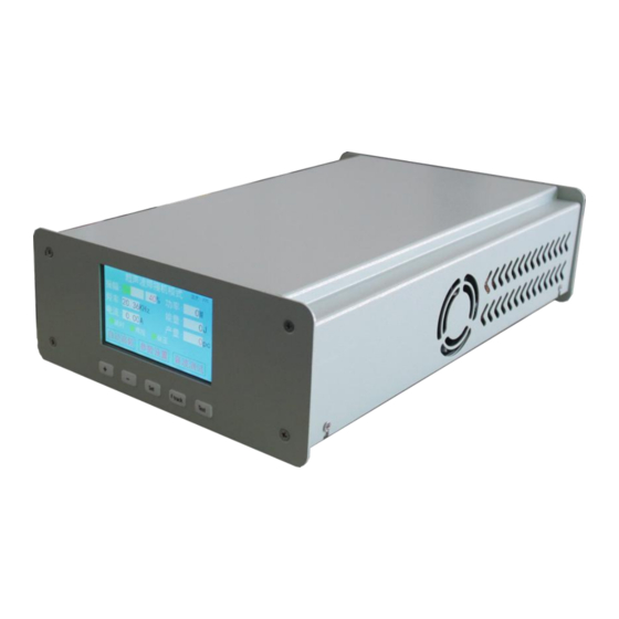
JYD-2700S Ultrasonic Welding Generator
User Manual
I. Basic information introduction
II. Environment Requirements
III. Connecting ports introduction
IV. Display interface and parameter introduction
V. The most common setup process for welding
applications
VI. Warning messages and possible causes
Advertisement

Summary of Contents for Ultrasonic JYD-2700S
- Page 1 JYD-2700S Ultrasonic Welding Generator User Manual I. Basic information introduction II. Environment Requirements III. Connecting ports introduction IV. Display interface and parameter introduction V. The most common setup process for welding applications VI. Warning messages and possible causes...
- Page 2 Color touch screen display: Through color screen and touch, friendly and easy-to-use human-computer interaction is achieved, and the experience is better. Slanted start: Ultrasonic energy supply and welding head are started at the most suitable ascent speed to reduce the system voltage.
-
Page 3: Environment Requirements
To ensure that the ultrasonic generator has good ventilation, care must be taken not to cover the generator's ventilation openings. It is strictly forbidden to use this equipment in adverse environment such as corrosive gas. The inhaled air will flow through the internal circuit module. - Page 4 The power plug must be inserted into a socket with a ground terminal. The adaptable power supply range of the ultrasonic signal generator is 220VAC ± 10% @ 50 / 60Hz. By adjusting the internal settings of the generator, it can also adapt to a power supply range of 110VAC ± 10% @ 50 / 60Hz.
- Page 5 Ultrasonic test: The maximum amplitude of the sonic test is 40% of the total amplitude. Even if your setting exceeds 40, if you want to exceed 40% of the output, you must use an external start. The purpose of this is to protect the mold to a certain extent to prevent irreversible damage caused by direct driving with large amplitude when the mold is abnormal (such as not being locked).
- Page 6 5. The most common setup process for welding applications: 1. Connect the transducer (transducer + amplifier + mould combination) through the 2-core aviation plug on the back of the device. 2. Connect the equipment to 220VAC power and turn on the power. 3.
- Page 7 Whether the load is connected to the mold during the frequency search, because the device searches for the resonance frequency with a very low amplitude. If a load is connected (such as searching for frequency in water), the driving capability is not enough to promote the load to obtain correct feedback.
- Page 8 During the working process, the system will continuously monitor the temperature of the power inverter part of the generator to ensure that it can prevent further temperature rise and damage the equipment in time when the temperature is too high. The design has fully taken into account the temperature generation and heat dissipation, and this protection does not occur under normal circumstances.
- Page 9 6.8 Error: 12V or 24V, 5V, 3V3, etc. The system detects that the core voltage is not within the set range. When this prompt occurs, try: Contact us If you still cannot find the cause after above testings, please contact us to resolve it.
Need help?
Do you have a question about the JYD-2700S and is the answer not in the manual?
Questions and answers