Table of Contents
Advertisement
Available languages
Available languages
Quick Links
Advertisement
Chapters
Table of Contents

Related Manuals for Temper Koban KP 2203


Summary of Contents for Temper Koban KP 2203
- Page 1 Pinza amperimétrica-vatimétrica KP 2203 Phase digital power clamp meter...
-
Page 2: Table Of Contents
KP 2203 Pinza amperimétrica - vatimétrica Índice Precauciones de seguridad Información de seguridad Símbolos de seguridad Descripción general Características Diseño del medidor Utilización del selector Utilización de los botones Pantalla LCD Realización de mediciones Medición de Tensión CA Medición de Corriente CA Medición de circuitos monofásicos Medición de circuitos trifásicos de 4 hilos Medición de circuitos trifásicos de 3 hilos... -
Page 3: Precauciones De Seguridad
KP 2203 Pinza amperimétrica - vatimétrica Precauciones de toma de corriente. • No exponga el aparato a la luz seguridad solar directa, a temperaturas extremas o a la humedad. Lea estas instrucciones de uso detenidamente y hasta el final ADVERTENCIA antes de comenzar a operar con su Lea las instrucciones antes de medidor. -
Page 4: Descripción General
KP 2203 Pinza amperimétrica - vatimétrica Descripción general Esta pinza amperimétrica-vatimétrica es un medidor portátil de potencia media, con medidor de corriente incorporado, el instrumento perfecto para la medición de energía. El medidor se compone de tres canales: tensión, corriente, potencia y un único chip microcontrolador. -
Page 5: Características
KP 2203 Pinza amperimétrica - vatimétrica Características Mide cinco parámetros de potencia en cada fase y el valor total de la potencia en Adaptado para la medición de la modo de medición trifásico potencia del circuitos trifásicos respectivamente. de tres hilos, trifásicos de cuatro hilos y circuitos monofásicos. -
Page 6: Diseño Del Medidor
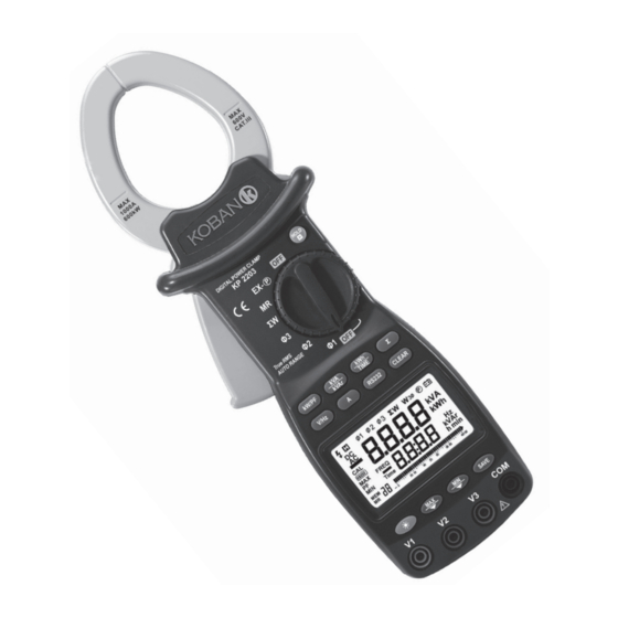
KP 2203 Pinza amperimétrica - vatimétrica Diseño del medidor Pinzas. Ф50mm Botón de retención de datos (HOLD). Retiene en pantalla el valor de la lectura, el símbolo se muestra en la pantalla LCD, pulsando el botón de nuevo, el medidor volverá al modo de medición normal. -
Page 7: Utilización Del Selector
KP 2203 Pinza amperimétrica - vatimétrica Puerto de Datos RS232C . La Φ2 SEGUNDO CANAL DE pinza amperimétrica puede MEDIDA. Para la toma de usar un Cable Puerto Serie entrada de medida V2. para comunicarse con una Φ1 PRIMER CANAL DE computadora. - Page 8 KP 2203 Pinza amperimétrica - vatimétrica Botón de Botón de medición de TIME retroiluminación energía activa por unidad de Botón de máximo tiempo. valor/ Botón de Presione el botón grabado previo TIME para medir la energía activa. Botón de valor El LCD mostrará...
- Page 9 KP 2203 Pinza amperimétrica - vatimétrica Botón de medida de Botón de máximo corriente. valor/ Botón de grabado previo. Presione el botón para Presione el botón para medir la corriente del circuito medir el valor máximo en modo y mostrar los valores leídos en medición.
-
Page 10: Pantalla Lcd
KP 2203 Pinza amperimétrica - vatimétrica Pantalla LCD 15. Símbolo de sobrecarga 16. Escala graduada a 100 17. Escala graduada a 40 Tensión peligrosa 18. Gráfico de barra Mantenimiento de datos 19. Pantalla de 4 dígitos (pantalla Primera fase secundaria) Segunda fase 20. -
Page 11: Realización De Mediciones
KP 2203 Pinza amperimétrica - vatimétrica Realización de mediciones Medición de la tensión CA Circuito Circuit 1000A 600V 600kW CAT.I FREQ HOLD Ture RMS AUTO RANGE kW / PF kVAr TIME V / Hz CLEAR RS232 FREQ FREQ SAVE Negro Amarillo Black Yellow... - Page 12 KP 2203 Pinza amperimétrica - vatimétrica Conecte las puntas de prueba mostrará el símbolo“MIN, el a la carga, presione el botón valor mínimo (TRMS) aparecerá y el valor medido se en la pantalla secundaria. V / Hz mostrará en la pantalla primaria Presiones el botón y el valor de la frecuencia de nuevo, el símbolo “MIN”...
-
Page 13: Medición De Corriente Ca
KP 2203 Pinza amperimétrica - vatimétrica la barra gráfica en el LCD. Puede observar la fluctuación de la medida en la escala de tensión. El primer modo es 0-20-40-60- 80-100, el segundo modo es 0-10-20-30-40. Conductor Tested conductor 1000A 600V hilo de neutro 600kW CAT .I II... - Page 14 KP 2203 Pinza amperimétrica - vatimétrica se mostrará en la pantalla secundaria. Presione el botón de nuevo para cancelar la medición del valor mínimo. Cuando la corriente exceda los 1000A (RMS), la pantalla mostrará el símbolo“OL”. (Figura 7). Existen dos maneras de mostrar la barra gráfica en el LCD.
-
Page 15: Medición De Circuitos Monofásicos
KP 2203 Pinza amperimétrica - vatimétrica Conductor medido Tested conductor 1000A 600V 600kW CAT.I Hilo de neutro Earth wire HOLD Tur e RMS AUTO RANGE kW / PF kVAr TIME V / Hz RS232 CLEAR RS232 SAVE (Figura 7. Corriente superior a 1000A) Medición de circuitos monofásicos (Figura 8. - Page 16 KP 2203 Pinza amperimétrica - vatimétrica Coloque las pinzas del medidor se mostrará en la pantalla y alrededor del conductor, de la la barra gráfica se mostrará carga o del circuito. completa. La entrada mínima Coloque el selector en una de de tensión es de 20V y la las posiciones Φ1, Φ2, Φ3, y entrada mínima de corriente...
- Page 17 KP 2203 Pinza amperimétrica - vatimétrica Conductor medido Tested conductor 1000A 600V 600kW CAT.I Hilo de neutro Earth wire HOLD Ture RMS AUTO RANGE kW / PF kVAr TIME V / Hz RS232 CLEAR SAVE Negro Black Verde Green (Figura 9. Corriente que excede los 1000A o tensión que excede los 600V) (2.) Potencia aparente (kVA) y aparente se mostrará...
- Page 18 KP 2203 Pinza amperimétrica - vatimétrica Conductor medido Tested conductor Hilo de neutro Earth wire 1000A 600V 600kW CAT.I I I HOLD Ture RMS AUTO RANGE kW / PF kVAr TIME V / Hz RS232 CLEAR kVAr kVAr SAVE Negro Rojo Black (Figura 10.
-
Page 19: Medición De Circuitos Trifásicos De 4 Hilos
KP 2203 Pinza amperimétrica - vatimétrica Medición de circuitos c. Los botones trifásicos de 4 hilos están innactivos en este modo de medición. Parámetro de potencia trifásico d. El valor máximo de significa potencia activa total, la energía activa es de potencia reactiva total, potencia “9999kWh”. - Page 20 KP 2203 Pinza amperimétrica - vatimétrica (Figura 12). el botón para medir kW / PF Gire el selector a la posición la potencia activa (kW) y el Φ2 (medición de la segunda coeficiente de potencia (PF). El fase), coloque las pinzas del valor medido se mostrará...
- Page 21 KP 2203 Pinza amperimétrica - vatimétrica Tested conductor Conductor medido 1000A 600V 600kW CAT.I I I Earth wire HOLD Hilo de neutro Ture RMS AUTO RANGE kW / PF kVAr TIME V / Hz RS232 CLEAR SAVE Black Red Green Yellow Negro Rojo Verde...
- Page 22 KP 2203 Pinza amperimétrica - vatimétrica (Figura 14. Mediciones de la potencia trifásica) Conductor medido Tested conductor 1000A 600V Hilo de neutro 600kW CAT.I Earth HOLD Ture RMS AUTO RANGE kW / PF kVAr TIME V / Hz RS232 CLEAR SAVE Negro Rojo Verde...
-
Page 23: Medición De Circuitos Trifásicos De 3 Hilos
KP 2203 Pinza amperimétrica - vatimétrica (Figura 16. Potencia aparente total trifásica) Conductor medido Tested conductor 1000A 600V 600kW CAT.I Hilo de neutro Earth wire HOLD Ture RMS AUTO RANGE kW / PF kVAr TIME V / Hz RS232 CLEAR kVAr kVAr SAVE... -
Page 24: Salvado De Las Mediciones
KP 2203 Pinza amperimétrica - vatimétrica Salvado de las mediciones como se muestra en la figura 18, luego gire el cable para fijarlo al medidor. Conecte el otro extremo En modo medición, presione el del cable a un Puerto serie de botón para guardar los SAVE... -
Page 25: Retroiluminación De La Pantalla
KP 2203 Pinza amperimétrica - vatimétrica M A X 6 0 0 V O P T IC A L IN T E R F A C E R S 2 3 2 (Figure 18. Conexión del cable RS232C) Retroiluminación de la de tensión como proveedor de potencia externa para funcionar. -
Page 26: Diagrama De La Curva De Potencia
KP 2203 Pinza amperimétrica - vatimétrica Diagrama de la Curva de Potencia (PF=KW / KVA) 2000W 2000W PEAK VALUE OF POWER (Figura 20. PF=1) =141V PEAK VALUE 1000W ACTIVE POWER POWER 180° 90° 360° =14A PEAK VALUE (Figura 21) 500W ACTIVE POWER KW= I R 180°... -
Page 27: Sustitución De Las Baterías
KP 2203 Pinza amperimétrica - vatimétrica Sustitución de las funcionamiento. Utilice el siguiente procedimiento para la sustitución de las baterías mismas: Desconecte las puntas de prueba de cualquier fuente de PRECAUCIÓN alimentación, gire el selector Para evitar descargas a la posición OFF, y retire las eléctricas, el aparato debe puntas de prueba delas tomas estar apagado y las puntas... -
Page 28: Especificaciones
KP 2203 Pinza amperimétrica - vatimétrica Especificaciones VOLTAJE CA VALOR EFICAZ (RMS) RANGO PRECISION RESOLUCION IMPEDANCIA DE ENTR. 100V ±(1.2%+5) 0.1V 10 MΩ (DERIVACIÓN 10Pf) 300V ±(1.2%+5) 0.1V 600V ±(1.2%+5) 0.1V Límite de sobrecarga: 750V (RMS) CORRIENTE AC RANGO PRECISION RESOLUCION ±(2%+5) 0.1A... - Page 29 KP 2203 Pinza amperimétrica - vatimétrica POTENCIA APARENTE (VA) RANGO PRECISION RESOLUCION 4kVA ±(3%+5) 0.01kVA 10kVA ±(3%+5) 0.01kVA 40kVA ±(3%+5) 0.01kVA 100kVA ±(3%+5) 0.01kVA 600kVA ±(3%+5) 0.1kVA Corriente mínima de medición: 5A Voltaje mínimo de medición: 20V COEFICIENTE DE POTENCIA (PF) 0.3~1 Capacitiva ±(0.02+2)
- Page 30 KP 2203 Pinza amperimétrica - vatimétrica ENERGÍA ACTIVA (kWh) RANGO PRECISIÓN RESOLUCIÓN 1~9999kWh ±(3%+2) 0.001kWh Corriente mínima de medición: 0.5A Voltaje mínimo de medición: 10V FREQUENCY ( Hz ) RANGE PRECISIÓN RESOLUCIÓN 20Hz~1kHz 0.5% 0.1Hz Voltaje mínimo de medición: 20V •...
-
Page 31: Contenido De La Caja
KP 2203 Pinza amperimétrica - vatimétrica Contenido de la caja Manual de usuario Baterías, 1.5V AA Puntas de prueba (MS3000) Pinza amperimétrica (MS3102) Cable RS232C ( MS3403 ) Software de registro gráfico de datos Maletín www.grupotemper.com Manual de instrucciones |... - Page 32 KP 2203 Phase digital power clamp meter Contents Safety Precautions Safety Information Safety Symbols General Description Features Meter Layout Using The Selector Using The Buttons Lcd Display Making Measurements Measuring AC Voltage Measuring AC Current Measuring Single-Phase Circuit Measuring Three -Phase Four-Wire Circuit Measuring Three -Phase Three-Wire Circuit Saving Measurement Recalling Memory...
-
Page 33: Safety Precautions
KP 2203 Phase digital power clamp meter Safety Precautions WARNING Read the instructions before using Read these operation instructions the instrument. thoroughly and completely before operating your meter. Pay particular attention to WARNING. The instructions in these warnings Safety Information must be followed. -
Page 34: General Description
KP 2203 Phase digital power clamp meter General Description Three-phase digital power clamp meter is a handheld aptitude meter with power measurement, it is incorporated current meter and power measurement instrument. The meter is composed of three channels: voltage, current, power and single chip Microcontroller. -
Page 35: Features
KP 2203 Phase digital power clamp meter Features measurement mode respectively. Multifunctional button control, For power measurement of there are double scales analogue 3-phase 3-wire circuit, 3-phase bar graph to display fluctuation 4-wire circuit, single-phase of voltage and current. circuit. With PC RS232C interface and The instrument can complete the special WINDOWS data graphics... -
Page 36: Meter Layout
KP 2203 Phase digital power clamp meter Meter Layout Clamp Jaws. Ф50mm HOLD Button. Holds the display reading and symbol is shown in the LCD display, press this button again, the meter return to normal measurement mode. Function Selector Rotary Switch. -
Page 37: Using The Selector
KP 2203 Phase digital power clamp meter Using the Selector Using the buttons Turn the meter on by rotating the (Table 2. Function Button) selector to any function as following. BUTTON DESCRIPTION Active Power, Power kW / PF (Table 1. Introducing The Selector) Factor Measurement ITEM DESCRIPTION... - Page 38 KP 2203 Phase digital power clamp meter press the button to sum Σ kW / PF Active Power, Power up again; press the Factor Measurement Button. button for the third Σ Press button to measure kW / PF phase after you getting the Active Power and Power Factor measured in measurement mode.
- Page 39 KP 2203 Phase digital power clamp meter meter and a computer, the Press button to measure communication function is minimum value in measurement working. mode, the display shows current minimum value in the secondary CLEAR Clear Memory display. Button. When you turn the selector to Press button for three MR, press...
-
Page 40: Lcd Display
KP 2203 Phase digital power clamp meter Lcd Display 14. Time unit : hour(h), minute(min) 15. Overflow symbol 16. 100 graduate scale Dangerous voltage symbol 17. 40 graduate scale Data holding symbol 18. Bar graph First phase symbol 19. 4 digit display ( For secondary Second phase symbol display ) Third phase symbol... -
Page 41: Making Measurements
KP 2203 Phase digital power clamp meter Making Measurements Measuring AC Voltage Circuit 1000A 600V 600kW CAT.I FREQ HOLD Ture RMS AUTO RANGE kW / PF kVAr TIME V / Hz CLEAR RS232 FREQ FREQ SAVE Black Yellow (Figure 3. Voltage Measurements) Turn the selector to one of lead into the COM input terminal Φ1,Φ2,Φ3, refer to Table 3 to... - Page 42 KP 2203 Phase digital power clamp meter Connect test leads to the load, shown in the secondary display. press button, voltage Press button again, the V / Hz measured value is displayed in “MIN” symbol is disappeared, the primary display and current the secondary display return to frequency value of voltage is current frequency value.
-
Page 43: Measuring Ac Current
KP 2203 Phase digital power clamp meter Measuring AC Current (Figure 5. Current Measurements) Tested conductor 1000A 600V 600kW CAT .I II Earth wire HO LD O FF Ture RMS AUTO RANGE O FF kV A kW / PF kV Ar TIME V / Hz RS232... - Page 44 KP 2203 Phase digital power clamp meter (Figure 6. Maximum Value Of Current Measurements) Tested conductor 1000A 600V 600kW CAT.I Earth wire HOLD Ture RMS AUTO RANGE kW / PF kVAr TIME V / Hz RS232 CLEAR SAVE (Figure7. Current Exceeds 1000A) Tested conductor 1000A 600V...
-
Page 45: Measuring Single-Phase Circuit
KP 2203 Phase digital power clamp meter Measuring Single-Phase Circuit (Figure 8. Single-phase Power Tested conductor Measurements) 1000A 600V 600kW CAT.I Earth wire HOLD Ture RMS AUTO RANGE kW / PF kVAr TIME V / Hz RS232 CLEAR SAVE Black Green Hook the clamp jaws around the ( 1. - Page 46 KP 2203 Phase digital power clamp meter exceeds 1000A, the “OL” c. Press button, the symbol will be shown in the maximum value of Active display too. And the bar graph Power is shown in the is full.(Figure 9) The minimum secondary display.
- Page 47 KP 2203 Phase digital power clamp meter ( 2. ) Apparent Power (kVA) and secondary display. Reactive Power ( kVAr ) d. Press button, the a. Press button, the minimum value of Apparent kVAr Apparent Power value is Power is shown in the shown in the primary display, secondary display.
- Page 48 KP 2203 Phase digital power clamp meter (3.) Active Energy (kWh) and the measured value of Active Time (hmin) Energy is larger. If you need a. In Active Energy read the Active Energy value measurement mode, voltage sometime, press the HOLD signal must be input into button, so the measured V1 and COM terminal of the...
-
Page 49: Measuring Three -Phase Four-Wire Circuit
KP 2203 Phase digital power clamp meter Measuring Three –Phase c. The button and button is invalid in Four-Wire Circuit Active Energy measurement mode. Three-phase power parameter means d. The maximum value of total Active Power, total Reactive Active Energy is “9999kWh”. Power, total Apparent Power, total If Active Energy value exceeds Power Factor. - Page 50 KP 2203 Phase digital power clamp meter second phase measurement), phase; press button again kVAr hook the clamp jaw around to measure Apparent Power the second phase conductor of and Reactive Power, after the the tested circuit, press kW / PF result is shown in the LCD, press button and button to...
- Page 51 KP 2203 Phase digital power clamp meter Tested conductor 1000A 600V 600kW CAT.I I I Earth wire HOLD Ture RMS AUTO RANGE kW / PF kVAr TIME V / Hz RS232 CLEAR SAVE Black Red Green Yellow kVAr (Figure 13.The Second Power Measurements) Turn the selector to Φ3( to the three-phase load (Figure 15).
- Page 52 KP 2203 Phase digital power clamp meter (Figure 14. The Third Phase Power Measurements) Tested conductor 1000A 600V 600kW CAT.I Earth HOLD Ture RMS AUTO RANGE kW / PF kVAr TIME V / Hz RS232 CLEAR SAVE Black Green Yellow kVAr (Figura 14.
-
Page 53: Measuring Three-Phase Three-Wire Circuit
KP 2203 Phase digital power clamp meter (Figure16. Total Apparent Power Of Three-Phase) Tested conductor 1000A 600V 600kW CAT.I Earth wire HOLD Ture RMS AUTO RANGE kW / PF kVAr TIME V / Hz RS232 CLEAR kVAr kVAr SAVE Black Red Green Yellow Measuring Three-Phase Three-Wire Circuit... -
Page 54: Saving Measurement
KP 2203 Phase digital power clamp meter Saving Measurement to a serial port of a computer. Then the meter can transmit measured data to computer by the infrared In measurement mode, you can press photoelectricity RS232C interface button to save the present SAVE in real-time mode. -
Page 55: Sketch Of Safety Holding
KP 2203 Phase digital power clamp meter M A X 6 0 0 V O P T IC A L IN T E R F A C E R S 2 3 2 (Figure 18. RS232C Interface Cable Connection) (Figure 19) Sketch Of Safety Holding Use the wrist-webbing to prevent a accidentally drop as shown in Figure... -
Page 56: Curve Diagram Of Power
KP 2203 Phase digital power clamp meter Curve Diagram Of Power ( PF=KW / KVA ) 2000W 2000W PEAK VALUE OF POWER (Figure 20. PF=1) =141V PEAK VALUE 1000W ACTIVE POWER POWER 180° 90° 360° =14A PEAK VALUE (Figure 21) 500W ACTIVE POWER KW= I R... -
Page 57: Replacing Batteries
KP 2203 Phase digital power clamp meter Replacing Batteries to replace the batteries: Disconnect test leads from any signals, turn the rotary function WARNING switch to OFF, and remove To avoid electrical shock , the the test leads from the input instrument must be power off terminals. -
Page 58: Specifications
KP 2203 Phase digital power clamp meter Specifications AC VOLTAGE RANGE ACCURACY RESOLUTION INPUT IMPEDANCE 100V ±(1.2%+5) 0.1V 10 MΩ (10Pf SHUNT) 300V ±(1.2%+5) 0.1V 600V ±(1.2%+5) 0.1V Max. Overload Voltage:750V (RMS) AC CURRENT RANGE ACCURACY RESOLUTION ±(2%+5) 0.1A 100A ±(2%+5) 0.1A 400A... - Page 59 KP 2203 Phase digital power clamp meter APPARENT POWER (VA) RANGE ACCURACY RESOLUTION 4kVA ±(3%+5) 0.01kVA 10kVA ±(3%+5) 0.01kVA 40kVA ±(3%+5) 0.01kVA 100kVA ±(3%+5) 0.01kVA 600kVA ±(3%+5) 0.1kVA Minimum measurement current : 5A Minimum measurement voltage : 20V POWER FACTOR (PF) 0.3~1 Capacitive ±(0.02+2)
- Page 60 KP 2203 Phase digital power clamp meter ACTIVE ENERGY (kWh) RANGE ACCURACY RESOLUTION 1~9999kWh ±(3%+2) 0.001kWh Minimum measurement current : 0.5A Minimum measurement voltage : 10V FREQUENCY ( Hz ) RANGE ACCURACY RESOLUTION 20Hz~1kHz 0.5% 0.1Hz Minimum measurement voltage: 20V •...
-
Page 61: Package Content
KP 2203 Phase digital power clamp meter Package content Users manual Battery, 1.5V AA Test Leads (MS3000) Connect test clamp (MS3102) RS232C interface cable ( MS3403 ) PC Data Record graph software Carry Case www.grupotemper.com Instructions manual |... - Page 62 KP 2203 Phase digital power clamp meter Instructions manual | www.grupotemper.com...
- Page 63 GARANTIE • GARANTIA years années anos TEMPER ENERGY INTERNATIONAL S.L. TEMPER ENERGY INTERNATIONAL garantiza este aparato por 2 años ante S.L. garantit cet apareil pour le durée todo defecto de fabricación. Para hacer de 2 annèes contre tout défault de válida esta garantía, es imprescindible...
- Page 64 TEMPER ENERGY INTERNATIONAL S.L. Polígono industrial de Granda, nave 18 33199 • Granda - Siero • Asturias Teléfono: 902 201 292 Fax: 902 201 303 Email: info@grupotemper.com Una empresa del grupo...
Need help?
Do you have a question about the Koban KP 2203 and is the answer not in the manual?
Questions and answers