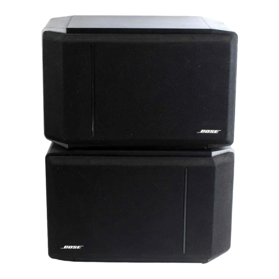
Summary of Contents for Bose 301 Series
- Page 1 ® ® ® SERIES IV DIRECT/REFLECTING SPEAKER SYSTEM Service Manual P/N 181850 REV 1 © 1996 Bose Corporation...
-
Page 2: Table Of Contents
301 Series IV Main Assembly Drawing ..................7 Figure 4: 301 Series IV Packaging Parts Drawing ..................8 TABLES 301 Series IV Main Assembly Parts List ....................9 301 Series IV Crossover Parts List ......................10 301 Series IV Main Packaging Parts List ....................10 PROPRIETARY INFORMATION... -
Page 3: Bose ® 301 ® Series Iv Technical Description
The sum of all these unique features makes the 301 Series IV speaker capable of reproducing the wide dynamic range demanded by today’s advanced recordings without strain or loss of clarity. -
Page 4: Disassembly/Assembly Procedures
DISASSEMBLY/ASSEMBLY PROCEDURES Note: Refer to Figure 3 for the following proce- tweeter from the molded bracket portion of the dures. endcap. 1. Grille Removal: Both the front grille (1) and the 3.4 Cut the wires connected to the tweeter as close side grille (3) are held in place by a snap-fit and to the tweeter terminals as possible. -
Page 5: Remounting The Grille
4.6 Remount the tweeter using the #8-32 screw. 4.7 Remount the woofer using the four #8-11 screws. 5. Remounting the Grilles: Both side and front grilles can only be mounted one way. 5.1 Side Grille: Align the feet with the fast-on grommets. -
Page 6: Test Procedures
TEST PROCEDURES Note: Before performing any tests, remove both Note: There should not be any buzzes or grilles by following the grille removal instructions in rattles from within the speaker cabinet. Re- dress any wire or component that buzzes. the disassembly section of this manual. 3. -
Page 7: Tweeter Phase Test
This ensures that the woofer and speaker input Note: Due to the inaccessibility of the tweeters, terminals are wired in phase, (see Schematic it may be necessary to remove the tweeters Diagram, Figure 2). from their respective endcaps. Refer to the Disassembly Procedures on replacing 6. - Page 8 See Detail A for Logo Variations and Placement Note: Exploded view of end caps is to show relative location of crossover components as well as the tweeters and is not intended to Detail A Logo Variations & Placement represent a serviceable part. ( Left Speaker Shown ) ®...
- Page 9 ® FIGURE 4: 301 Series IV Packaging Parts Drawing...
-
Page 10: 301 Series Iv Main Assembly Parts List
Series IV Main Assembly Parts List (Figure 3) ® Item Description Part Number Q t y . Reference Number Speaker Grille Assembly, Front: Brown/Grey 181851-01 Black 181851-00 Nameplate, Logo: Large 122812-0 Small 185208-01 Grille Assembly, Side: Dark Brown 181856-01 Black 181856-00 Tweeter, 3"... -
Page 11: 301 Series Iv Crossover Parts List
Notes: 1. C2 is mounted to the surface of the woofer basket using foam tape P/N 118223. 2. This part is not normally stocked as a service part. 301 Series IV Main Packaging Parts List (Figure 4) Item Description Part Number Q t y . - Page 12 SPECIFICATIONS AND FEATURES SUBJECT TO CHANGE WITHOUT NOTICE Bose Corporation The Mountain Framingham, Massachusetts USA 01701 FOR TECHNICAL ASSISTANCE AND PARTS ORDERING, CALL 800-367-4008 P/N 181850 7/96 REV. 1...


Need help?
Do you have a question about the 301 Series and is the answer not in the manual?
Questions and answers