
Summary of Contents for VR Avionics LSI
- Page 1 Log Sync Interface user guide Updated: 28 September 2021 Copyright 2021 by VR Avionics...
- Page 2 VR Avionics, Inc. VR Avionics hereby grants permission to download a single copy of this manual and of any revision to this manual onto a hard drive or other electronic storage medium to be viewed for personal use,...
-
Page 3: Table Of Contents
LSI user guide Contents Operation........................4 Logging Data..................................4 Synchronizing History...............................5 Interfacing via USB................................6 Doing Diagnostic Tests...............................7 Adjusting Configuration Settings..........................8 Updating Firmware...............................9 Installation........................10 Electrical Connection...............................10 Mounting Considerations..............................10 Configuration.......................11 General Settings................................11 CAN Bus Interface Speed............................11 Log File Incremental Reference Number......................11 09/28/21 ©... -
Page 4: Operation
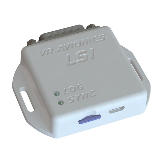
VR Avionics line-replaceable units (LRU's) constantly send out detailed operational information over CAN bus, and the LSI is able to capture and log all of it to memory card – a micro SD card in this case. This card can be left in the LSI without much worry of running out of memory, and should something of interest have occurred during a passed flight, the card can then be extracted and the log file conveniently inspected on a PC. -
Page 5: Synchronizing History
The LSI will create a new history file inside the HIST folder only if logs with a size larger than zero was retrieved. Each history file is named MMMMSSSS_#.VRH where MMMM constitutes the LRU name (for example “TSLM”), SSSS constitutes the LRU serial number, and # a unique number that automatically... -
Page 6: Interfacing Via Usb
LSI user guide Interfacing via USB To perform certain maintenance tasks a USB cable may be used to connect the LSI to a Windows PC (laptop, desktop, or tablet). The LSI accepts a micro USB type B plug. On the PC, our SetView software (available from vravionics.com) should be installed. Plugging in the USB cable will introduce a new COM port (for example “COM5”). -
Page 7: Doing Diagnostic Tests
LSI user guide Doing Diagnostic Tests To perform a diagnostic test for a particular LRU, ensure this LRU's tab is selected on the bottom right side of the Dash panel in SetView (see example in previous section). Now select the diagnostic test you want performed from the SetView top menu: System →... -
Page 8: Adjusting Configuration Settings
LSI user guide Adjusting Configuration Settings To make adjustments to the configuration settings of any LRU (including that of the LSI), select from the SetView top menu: System → Adjust Configuration The example below shows the configuration adjust tab for a LSI with connected TSLM. -
Page 9: Updating Firmware
System → Change Application Starting with a dialog box asking whether to update the LSI firmware, subsequent dialog boxes will ask the same for those LRU's. Below is an example of a dialog box for a TSLM with serial number 8020: Click Update to update, and Cancel to skip updating specific LRU firmware. -
Page 10: Installation
Electrical Connection Electrical connection of the LSI is via only four wires – power and ground as well as the two CAN bus lines, CAN-H and CAN-L. It works from 12V or 24V aircraft electrical systems and draws very little current. -
Page 11: Configuration
The LSI have adjustable configuration settings that determine how it functions. These settings can be accessed by Windows laptop or PC running our SetView software connected via USB cable to the LSI. These settings can be viewed by performing from SetView a “Synchronize”, and adjusted by performing an “Adjust Configuration”...
Need help?
Do you have a question about the LSI and is the answer not in the manual?
Questions and answers