Advertisement
Table of Contents
- 1 Mounting the Dopplerfx Accessory Board
- 2 Powering the Dopplerfx Accessory Board
- 3 How to Operate Your Dopplerfx Accessory Board
- 4 Setting the Observer Position
- 5 How Do I Know When I Have a Satellite Fix?
- 6 The Dopplerfx Led Indicator
- 7 Using System Sounds for Dopplerfx Event Notifications
- 8 The Dopplerfx Backup Battery
- Download this manual
This is a Quick Start Guide only. For comprehensive instructions, please read the
DopplerFXReferenceManual.pdf
that is in the sound module. Insert the microSD Card into the included USB microSD card reader and
insert that into one of your computer's USB ports.
For the ShockWave 3 Reference manual, please refer to the
also located in the Manuals-Instructions folder on the microSD card.
CHAPTER 1 - MOUNTING THE DOPPLERFX ACCESSORY BOARD
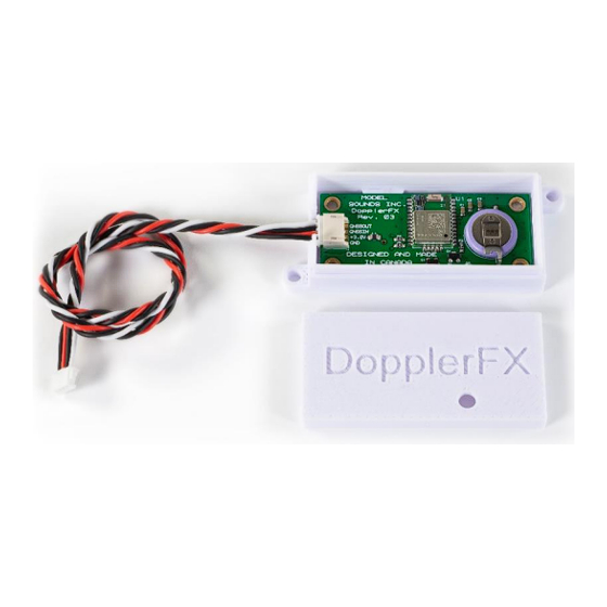
The DopplerFX board is shipped mounted inside its plastic case with the 4-wire cable connected as
shown here. The lid will already be installed.
Then, replace the lid on top with the LED hole above the LED. Press the lid firmly home so that its
retention indents lock into the corresponding bumps on the case.
Use the supplied hook and loop fastener patch to attach the case, with the lid uppermost, to the inside
top of your fuselage. Additional glue may be required to attach the hook and loop fastener securely to
your fuselage especially when it is left out in the sun and heats up. For foam aircraft, the use of Beacon
Adhesives Inc. Foam-Tac glue is recommended.
In this way the GNSS antenna will be facing upwards and towards the sky when the model is flying level
the right way up.
Keep the DopplerFX Accessory board as far away as possible from all other electronics and metal or
carbon fibre structures as they can interfere with the very weak GNSS satellite signals.
®
DopplerFX
Rev. 03 Quick Start Guide
document in the Manuals-Instructions folder on the microSD Card
Figure 1 - DopplerFX Accessory Board In its Plastic Case
Page
© Model Sounds
ShockWave3HWReferenceManual.pdf
If the cable should become loose, the lid must
be removed in order to push the connector
fully home.
If you need to adjust the cable connector,
remove the lid by gripping the case sides (not
the lid sides), pushing them in slightly and
lifting off the lid. With the lid off it is much
easier to fully insert the cable plug into its
connector on the board.
of 4
1
TM
Inc.
Published: November 12, 2020
Advertisement
Table of Contents

Related Manuals for MODEL SOUNDS DopplerFX

Summary of Contents for MODEL SOUNDS DopplerFX
- Page 1 In this way the GNSS antenna will be facing upwards and towards the sky when the model is flying level the right way up. Keep the DopplerFX Accessory board as far away as possible from all other electronics and metal or carbon fibre structures as they can interfere with the very weak GNSS satellite signals.
- Page 2 Position and to remotely enable and disable the DopplerFX feature. Pin 1 is system GND, or battery –ve, pin 2 is receiver power, pin 3 carries the DopplerFX RC receiver signal from the radio receiver into the ShockWave 3 board.
- Page 3 Subsequently, as long as the backup battery is charged, and if you power-up the ShockWave 3 and DopplerFX board in roughly the same location as last time, this time will be much less – just a few seconds. This is called a “hot-start”. Please be patient during this time as it is important this time be allowed for the Observer Position to be obtained.
- Page 4 CHAPTER 5 – THE DOPPLERFX BACKUP BATTERY When a GNSS receiver is first powered up it does a “Cold Start”. This means that it searches for available satellites and builds a small database of available start-up information and other essential data.
Need help?
Do you have a question about the DopplerFX and is the answer not in the manual?
Questions and answers