Table of Contents
Advertisement
Quick Links
Instruction Manual
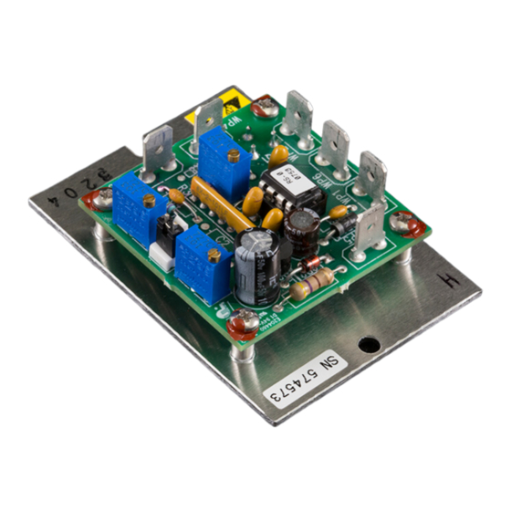
Model TC-24-10
Thermoelectric Cooler
Temperature Controller
Drawing #3170 Rev. I
TE
15 90 K ean e Dr i ve
Tr a ver se Ci ty , M I 49 6 96 U SA
Web :
w ww .tet ech
. com
All Materials Copyright © 2012, TE Technology, Inc.
for
October 16, 2015
TECHNOLOGY, INC.
Ph on e : ( 23 1) 92 9 -3 9 66
Fa x:
e-m a il :
®
( 23 1) 9 29 - 41 63
coo l@ tete ch .c o m
Advertisement
Table of Contents

Subscribe to Our Youtube Channel
Related Manuals for TE Technology TC-24-10

Summary of Contents for TE Technology TC-24-10
- Page 1 Tr a ver se Ci ty , M I 49 6 96 U SA Fa x: ( 23 1) 9 29 - 41 63 Web : w ww .tet ech . com e-m a il : coo l@ tete ch .c o m All Materials Copyright © 2012, TE Technology, Inc.
- Page 2 THE LATEST REVISION OF THIS MANUAL IS AVAILABLE AT www.tetech.com. Verify that you are using the latest revision available. The TC-24-10 should not be used as a toy, or serious injury could result. The TC-24-10 should only be used for its intended purpose of providing temperature control of TE Technology’s thermoelectric devices only.
- Page 3 Inc. from and against, any losses, costs, expenses (including reasonable attorneys’ fees), injuries, liabilities or damages of any kind or nature whatsoever, arising out of the use or inability to use this TE Technology, Inc. product, from the omission or failure to use protection devices, or from failure to comply with this manual. This provision is in addition to any other indemnification provisions which are a part of the Purchase Order or contract with Purchaser.
-
Page 4: Table Of Contents
Controller Wiring Diagram (One Power Supply Setup) ..............17 Controller Wiring Diagram (Two Power Supplies Setup) .............. 18 Mechanical Package Drawing ....................... 19 Temperature vs. Sensor/Potentiometer Voltage (graphs) ............20 Temperature vs. Sensor/Potentiometer Voltage (table) .............. 21 Thermistor Styles for TC-24-10 ..................... 22... -
Page 5: Features
Features TC-24-10 Temperature Controller The TC-24-10 is a heat- or cool-only temperature controller for thermoelectric (TE) devices. It can also be used with resistive heaters. The basic components of the TC-24-10 are a microprocessor, a thermistor input, a power output stage, and potentiometers located on the controller’s circuit board to adjust the temperature set point,... - Page 6 The controller’s operating temperature range is 0 °C to 50 °C ambient. The range can be extended to 70 °C with proper heat-sinking. If the controller is to operate in an ambient greater than 50 °C, consult with TE Technology engineers for further assistance.
- Page 7 9 V, but no more than 26 V. If the TE device operates on less than 9 V, the TC-24-10 can be configured to use two power supplies. The power supply for the controller electronics must be able to provide (9 to 26) V at 150 mA current minimum. The power...
-
Page 8: Operating Instructions
Regardless of whether you use one or two power supplies, when making a cooling system from a single TE module, the maximum operating voltage for that system is usually no more than 75% of the rated Vmax of the TE module. The 75% rule is based on the TE module being thermally connected to a “good”... - Page 9 Connect the thermistor wire leads to WP3 and WP4. The TC-24-10 can be used with two separate power supplies which allows for the control of TE devices whose nominal operating voltage is less than 9 V. In this case, one power supply is for the TE device, and the other power supply is for the controller itself (the microprocessor and associated electronics).
- Page 10 It is further recommended that such devices require the user to remove and correct the root cause of a fault before allowing the TC-24-10, the load, and related equipment to be re-energized. Protection devices should include, but are not limited to: •...
- Page 11 THE APPROPRIATE CONTROL TEMPERATURE HAS BEEN SET. The TC-24-10 does not have a display for indicating the set temperature or sense temperature. However, you can measure the sensor (thermistor) voltage across WP3 to WP4, and the set point voltage across Pin 2 (+) to Pin 3 (-) on potentiometer R7.
- Page 12 Turn off the power to the controller and connect the TE device to the controller: COOLING MODE: One Power Supply Operation a) Connect the positive terminal (+) of ONLY the TE device to WP1. b) Connect the negative terminal (-) of ONLY the TE device to WP2. c) Verify that JP1 is shorted (that is, a jumper is installed, which is the factory default).
- Page 13 TE Technology’s standard thermoelectric cooling assemblies (TCA) have at least one fan on the heat sink. The standard configuration has the thermoelectric modules and fan(s) wired to a terminal block with jumpers across the terminals so that the fans and modules are connected in parallel. However, this configuration is applicable only when applying power directly from the power supply.
-
Page 14: Control Function Description
Turn on power supply to the controller (and power supply to the TE device if applicable), and set tuning parameters as necessary. Controller tuning is discussed in section 3. Do not mount the controller to a surface which is exposed to a source of heat, such as from electronics, machinery, or solar radiation. -
Page 15: Controller Tuning
3.0 Controller Tuning Tuning of Proportional and Integral (PI) control requires knowing two parameters: 1. The natural period of the system, and 2. The bandwidth used to achieve this cycle. This tuning method follows the Ziegler Nichols closed-loop tuning principals. Briefly, the controller will first be set to a low gain (high Bandwidth) setting with no integral function (Integral rate = 0). - Page 16 Double the bandwidth calculated in section 3.6, and then adjust the Proportional Bandwidth Potentiometer to this new value. Fully counterclockwise = 0.5 °C, and fully clockwise = 5 °C. Each full turn of the Proportional Bandwidth Potentiometer corresponds to 0.18 °C increment. If doubling the bandwidth yields a value greater than 5 °C, set the bandwidth to 5 °C.
-
Page 17: Controller Wiring Diagram (One Power Supply Setup)
When one or more external fans are used on the TE device, these should be wired directly to a fixed voltage power supply for constant operation. When connecting the controller to a TE Technology Thermoelectric Cooling Assembly (TCA) verify that the electrical jumpers (shorts) located on the TCA terminal block are installed/removed per the TCA... -
Page 18: Controller Wiring Diagram (Two Power Supplies Setup)
Controller Wiring Diagram (Two Power Supplies Setup) -
Page 19: Mechanical Package Drawing
Mechanical Package Drawing PROPORTIONAL BANDWIDTH POTENTIOMETER HEAT/COOL MODE JUMPER 45.7 SET TEMPERATURE POTENTIOMETER INTEGRAL RATE POTENTIOMETER 38.1 3.96 69.8 63.5 Ø3.96 50.8 NOTE: ALL DIMENSIONS IN MILLIMETERS... -
Page 20: Temperature Vs. Sensor/Potentiometer Voltage (Graphs)
Temperature vs. Sensor/Potentiometer Voltage (graphs) Sensor Voltage Vs. Temperature -20 -12 -4 12 20 28 36 44 52 60 68 76 84 92 100 Temperature (°C) Potentiometer Voltage Vs. Set-point Temperature -20 -12 -4 12 20 28 36 44 52 60 68 76 84 92 100 Temperature (°C) -
Page 21: Temperature Vs. Sensor/Potentiometer Voltage (Table)
Temperature vs. Sensor/Potentiometer Voltage (table) Sensor voltage is measured across WP3 and WP4. Set-point voltage is measured across Pin 2 (+) and Pin 3(-) on R7 potentiometer. Sensor Set-point Sensor Set-point (thermistor) Potentiometer (thermistor) Potentiometer Temperature (°C) Voltage (V) Voltage (V) Temperature (°C) Voltage (V) Voltage (V) -
Page 22: Thermistor Styles For Tc-24-10
Thermistor Styles for TC-24-10 www.tetech.com for additional thermistors Note: all dimensions in millimeters. Some styles do not include fast-on terminals. Ø3.61 25.4 (2) 26 AWG STRANDED WIRE, THRU UL1430, IRRADIATED CROSS-LINKED EPOXY FILL PVC INSULATION, ORANGE 3.18 3.94 6.35 SQ. - Page 23 Temperature versus Resistance for MP-3238, MP-2444, and MP-2542 Thermistors 146735 146735 46709 46709 17136 17136 7075 7075 3227 3227 1601 1601 138447 138447 44397 44397 16388 16388 6801 6801 3115 3115 1551 1551 130677 130677 42213 42213 15676 15676 6539 6539 3008 3008...
Need help?
Do you have a question about the TC-24-10 and is the answer not in the manual?
Questions and answers