
Summary of Contents for I-Tech DA001
- Page 1 1CD monitor DA001OSD operation l-TECH C O M P A N Y i-Tech Company LLC 8 • EMAIL: info@itechlcd.com • WEB: www.iTechLCD.com TOLL FREE: (888) 483-24'...
-
Page 2: Safety Instruction
Safety Instruction Read and follow these instructions when connecting and using your LCD monitor: Operation: Keep the monitor out of direct sunlight and away from stoves or any other heat source. Remove any object that could fall into ventilation holes or prevent proper cooling of the monitor’s electronics. -
Page 3: Product Installation
Product Installation Switch off the power on both your monitor and your computer. The Power Switch is located in the right of the monitor. Connect the power cord to the AC outlet, and connect the power to the monitor through the AC/DC adapter. VGA Signal-Plug one end of the 15-pin signal cable to the video signal connector at the rear of the PC system and the other end to the monitor. -
Page 4: Control Functions
Control Functions The Monitor control functions are located on the lower side of the panel. The control key description 1. MENU Activate the on-screen-display function Down / Brightness control Brightness control Auto AUTO-ADJUSTMENT Power Switch Description 1. Menu Press the Menu key to activate the on screen display screen. It is a toggle key. Press twice to turn off the OSD. -
Page 5: Adjusting The Monitor
DJUSTING THE MONITOR The LCD monitor is designed to work with a range of compatible video adapters on the market. Due to the possible deviations between these video adapters, you may make some adjustment to fit the monitor for adapter used. ADJUSTMENT PROCEDURE First, you must activate the OSD screen through pressing the MENU key, the screen will show in the center of screen as below:... -
Page 6: Brightness Adjustment
AUTO-ADJUSTMENT WE STRONGLY RECOMMEND THAT YOU USE THIS ITEM TO GET THE OPTIMIZED VISUAL QUALITY. Use the ∇ & ∆ key to select auto-adjustment, and then press Menu Key to get the optimized quality. Or press Auto Key to get the optimized directly. BRIGHTNESS ADJUSTMENT Use the ∇... - Page 7 best Screen Settings optimization. H.Position ∇ ∆ Use the & key to select the H.Position item, then press Menu Key to get the best optimization. Use the ∇ & ∆ key to adjust H.Position value. Then press menu key to confirm. ...
-
Page 8: User Color
Phase ∇ ∆ Use the & key to select the Phase item, then press Menu Key to get the best optimization. ∇ ∆ Use the & key to adjust increase or decrease video Quality of the picture. ... -
Page 9: Language Setting
Auto Gain ∇ ∆ Use the & key to select Auto Gain, then press Menu Key to get the best color optimization that will be activated the auto adjusting input video color level for the picture. sRGB ∇... -
Page 10: Osd Setting
OSD Setting ∇ ∆ Use the & key to select the OSD Setting item, then press Menu Key to get the OSD setting selection. You could set up the property of Position, Display Timer, and Transparency of OSD menu. Volume ∇... -
Page 11: Troubleshooting
Trouble Shooting If your monitor fails to operate correctly, consult the following chart for possible solution before calling for repairs/RMA. Condition Possible Solution 1. Check if the signal cable is The screen is not synchronized? firmly seated in the socket. 2. - Page 12 AtoD BOARD DA001 Model:...
-
Page 13: General Function
1. GENERAL FUNCTION A. Power On System On ( AC power On auto turn on ) B. Auto Signal Source detect C. OSD up/ down for Brightness D. TFT-LCD Module Driver Board E. Resolution up to 1920X1200@75Hz (Note1) F. 15 Pin D-SUB VGA Connector input G. -
Page 14: Specification
67.5 VESA 1920x1200 74.5 **** Display Resolution depends on panel spec. Specification Model DA001 Panel Compatibility Compatible with XGA, SVGA, VGA resolution TFT LCD panel from various panel manufactures by Changing some jumpers setting and specified BIOS. Maximum Resolution Up to 8 bits per color, total 16.7M Colors... - Page 15 3. Signal input connections 4-1 VGA Signal Input Location J3 - 15 pin Hi-Density Female D-SUB Pin Assign and Definition Pin No. SYMBOL Pin No. SYMBOL Pin No. SYMBOL RED IN R-GND GREEN IN G-GND SDA DDC BLUE IN B-GND SYNC.
- Page 16 Remote (CN6) WAFER 3pin 2.0mm FUNCTION FUNCTION Motion Light Sensor Power DC ( CN9) WAFER 2pin 2.0mm FUNCTION FUNCTION Power DC ( CN10) WAFER 2pin 2.0mm FUNCTION FUNCTION +12V 4-3 Power Input Location - Jl : DC JACK DC=2.0mm 12V / 2A For 2 Light Inverter or 12V / 3A for 4 Light Inverter 4-4.LVDS OUTPUT Location - CN3 :2X15 PIN, PITCH 2.0mm Pin Assign and Definition...
- Page 17 LCD TTL OUT (J4) FUNCTION FUNCTION DCLK www.itechlcd.com...
- Page 18 4-6 Inverter Connector Location - CN1: 6 PIN WAFER PITCH 2.0mm 90D Pin assign and definition Pin No. SYMBOL Pin No. SYMBOL +12V ON /Off Adjust 4-6A. Inverter Current Adjust : Range 0 ( Inverter Current Max ) to 5V ( Inverter Current Min) or PWM ( 100% Current Max ) ( 10% Current Min) Frequency : 200HZ 4- 6B.
-
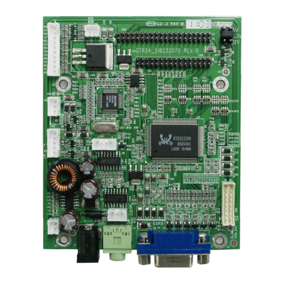
Page 19: Pcb Dimension
4. PCB DIMENSION 2.1 Dimension: 85mm (L) *100 mm (W)* 14.2mm (H) www.itechlcd.com...