Table of Contents
Advertisement
user manual
r/c tank Multifunctional module
The IBU3 module is a totally new board, based on experiences with IBU2, it offers superior performance combined with
flexibility and ease of use.
The IBU3 module completely replaces the electronics present in the RC Tank, allowing to fight according to the IR Tamiya
standards, customize all the sound effects and use a proportional radio from 4 to 8 channels (AM, FM, or 2.4 GHz) for full
tank control.
IBU3 User Manual rev. 1.0
I.B.U. Electronics
http://www.ibu-electronics.com
Advertisement
Table of Contents

Summary of Contents for I.B.U. Electronics IBU3
- Page 1 The IBU3 module completely replaces the electronics present in the RC Tank, allowing to fight according to the IR Tamiya standards, customize all the sound effects and use a proportional radio from 4 to 8 channels (AM, FM, or 2.4 GHz) for full tank control.
-
Page 2: Main Features
4 turret sounds , cannon, MG1, MG2, 5 mechanical noises, 2 hit sounds (random logic), tank destruction, rebirth 4 optional sounds selectable by remote control Audible alerts: Start system, low battery, empty battery, inactivity (transmitter or IBU3 module) Intelligent remote control calibration with acquisition and automatic matching of channels-to-function with test page ... - Page 3 In order to avoid faulty operation, follow the instructions described below Do not connect anything to the expansion connector, it is dedicated to additional modules (when available) Risk of permanently damaging the IBU3 Module In case of failure to comply with these instructions no warranty will apply IBU3 User Manual rev.
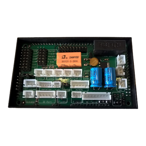
- Page 4 IBU3 Module CONNECTIONS Connect receiver channels receiver as shown in the figure, the polarity of the signal (orange) is turned towards the outer edge of the module IBU3 (For clarity only the first channel is connected) Connect the servos as shown in the figure, the polarity of the signal...
- Page 5 If you intend to use the volume pot remove the AB bridge and connect the cable to related connector. If using the remote volume control (using one radio channel, see the section in IBU3 Configurator) you can omit the volume control, in this case the AB bridge must be inserted.
- Page 6 Configurator IBU3). SM R connector The IBU3 module allow to use a smoke unit such as TARR Smoker or similar who have cables for the separate heating resistor. Connect this output to these cables. (Maximum relay load = 3 amps) SM P connector ...
- Page 7 Tamiya TBU connectors The IBU3 module allows you to use Tamiya IR unit without changes. Connect the IR receiver cable to the receiver connector and the LED to LED connector IR Port Connector Connect the IR cable (Heng Long/Taigen) to this connector Range jumper ...
- Page 8 Connect the cable from HL/Taigen Xenon module T Recoil connector The IBU3 module allows you to control the Tamiya recoil unit without changes by connecting the cable to this port Heng Long/Taigen turret port Taigen recoil connector The IBU3 module allows to drive the new Taigen recoil units for airsoft tanks without changes.
- Page 9 ML connector Connect the Left motor BATT connector Connect power from the battery MR connector Connect the Right motor IBU3 User Manual rev. 1.0 I.B.U. Electronics http://www.ibu-electronics.com...
- Page 10 Hardware built in protections The IBU3 Module is equipped with internal protections. The 16 Ampere 5x20 Fast Action Fuse (which is the only part serviceable by the user) protects the powertrain The PTC Resettable fuse (service fuse) protects the all the electronics, in case short circuit or wrong connections this fuse will disconnect the main supply coming from battery.
- Page 11 Connect your PC to IBU3 module using a USB cable Male / Male Type A (not supplied) CAUTION despite the USB port of IBU3 module is protected against short circuits is recommended to connect to the PC usb ONLY with IBU3 module switched off Power the IBU3 module ...
- Page 12 Switch between languages If the IBU3 module is not connected (and powered) to the PC you can not access the above user functions. Before you access the various functions of the program you must select the PC communications port...
- Page 13 After selecting the number of channels of your transmitter press the Start calibration button and follow the instructions on the screen, at the end of the configuration it will be automatically saved in the memory of IBU3 module. IBU3 User Manual rev. 1.0 I.B.U.
-
Page 14: Radio Configuration
After configuration save the settings by clicking on the command write IBU3 User Manual rev. 1.0 I.B.U. Electronics http://www.ibu-electronics.com... - Page 15 Gearbox setup In the upper part of the page are always displayed: current firmware version, serial number of IBU3 module and the battery voltage level. The button "Factory Settings" enables a parameter reset by restoring the default settings The first configuration page is dedicated to gearboxes , where you can set the parameters related to the maximum current, the rotational power (SuperSpin), the speed of the motors (right and left), the limitation of reverse speed.
-
Page 16: Configuration Setup
By checking the box inertia simulation will be active when you turn on the system. You can choose different curves of inertia by clicking on configuration and then choosing one of the six pre-programmed curves. IBU3 User Manual rev. 1.0 I.B.U. Electronics http://www.ibu-electronics.com... - Page 17 Also the rear lights will be lit simultaneously simulating the stops. After configuration save the settings by clicking on the command write. IBU3 User Manual rev. 1.0 I.B.U. Electronics http://www.ibu-electronics.com...
-
Page 18: Miscellaneous Setup
In case of problems of stability in the neutral position of the turret rotation is possible to set, as for the previous option, a percentage offset within which any fluctuations are not considered. IBU3 User Manual rev. 1.0 I.B.U. Electronics http://www.ibu-electronics.com... - Page 19 Tamiya recoil unit can be connected to T Recoil port. The standard HL/Taigen Recoil unit (or airsoft unit) the standard HL turret connector is used. After configuration save the settings by clicking on the command write. IBU3 User Manual rev. 1.0 I.B.U. Electronics http://www.ibu-electronics.com...
-
Page 20: Servo Setup
In the future it will be released the Halftrack functionality and this servo (if selected Halftrack mode) will be dedicated to the steering. After configuration save the settings by clicking on the command write. IBU3 User Manual rev. 1.0 I.B.U. Electronics... -
Page 21: Sound Setup
There are no restrictions in format or length of the file name, also there is not a sound file size limit, as long as you do not exceed the maximum available memory capacity, the module's physical memory is 16 Mbytes. Also it can be used with proprietary audio file .ibu extension that are available for free download IBU3 User Manual rev. 1.0 I.B.U. Electronics http://www.ibu-electronics.com... - Page 22 In addition to the usual audio effects are some new effects related to the functionality of IBU3 module. "Power on” file lets you store a sound that plays when the IBU3 Module is initialized and ready to use. The files "Battery Low" and "Battery cut-off" are two sounds played when the battery level is at the minimum, and when the safety cut- off occurs.
- Page 23 (Delta) Frequency shift - With this control you can set the maximum change in engine sound frequency depending to stick position. The sound of a real engine varies in frequency in relationship with RPM, the particular IBU3 audio management allows to simulate the variation of the frequency with throttle stick position (Delta) Volume variation - With this control you can set the maximum variation of the engine sound volume depending to stick position.
-
Page 24: Firmware Update
After downloading the new .dfu file from the main page press the button Firmware Update Make sure the module in update mode IBU3 checking that the green LED blinks slowly It will automatically open the browse files tab, browse through the folders and select the path where the .dfu file was saved... - Page 25 The output test function allows to check the IBU3 module functionality and the devices connected to it without having to use the radio. Ticking the boxes for the outputs they are activated allowing you to verify proper operation...
- Page 26 The RADIO test function allows you to check the functionality of the transmitter and the correct calibration with IBU3 module Moving the stick/slider/switch for the available channels you can check whether the calibration was successful IBU3 User Manual rev.
Need help?
Do you have a question about the IBU3 and is the answer not in the manual?
Questions and answers