Table of Contents
Advertisement
Quick Links
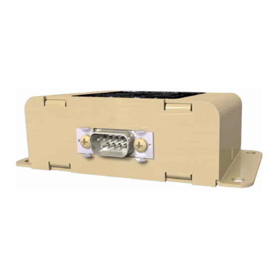
JA40-001 Intercom Tie Line Isolation Transformer
Data Sheet
Description
The JA40 Intercom Tie Line Transformer allows up to 4 tie lines to be transformer
coupled with a minimum crosstalk and noise interference.
Typical Application
JA9X
AUDIO CONTROLLER
JA9X
AUDIO CONTROLLER
TM
JA40-001 Data Sheet Rev A.pdf
JA40-001
ISOLATION TRANSFORMER
ICS TIE LINE
ICS TIE LINE
1959 Kirschner Rd, Kelowna, BC V1Y 4N7
Tel: (778) 478-2232 Toll-Free: (855) 478-2232
www.jupiteravionics.com
JA9X
ICS TIE LINE
AUDIO CONTROLLER
JA9X
ICS TIE LINE
AUDIO CONTROLLER
TO ONLINE INFO
Advertisement
Table of Contents

Summary of Contents for Jupiter Avionics JA40-001
- Page 1 JA40-001 Intercom Tie Line Isolation Transformer Data Sheet Description The JA40 Intercom Tie Line Transformer allows up to 4 tie lines to be transformer coupled with a minimum crosstalk and noise interference. Typical Application JA40-001 ISOLATION TRANSFORMER JA9X JA9X ICS TIE LINE...
- Page 2 PART NO. SHEET APPROVED 2k ohm 2k ohm L00N3 JA40-001 MATERIAL: CONFIDENTIAL & PROPRIETARY JA40-001 3D Model Rev A.SLDDRW DOC. NO. TO JUPITER AVIONICS CORP. FINISH: JUPITER AVIONICS TEMPLATE SOLIDWORKS LANDSCAPE SIZEA.DRWDOT 2k ohm 2k ohm Environment and Performance Operating Temperature...
- Page 3 JA40-001 ICS Tie Line Isolation Transformer Installation Manual Rev. B Jupiter Avionics Corporation 1959 Kirschner Road Kelowna BC Canada V1Y 4N7 Tel: +1 778 478 2232 Toll-Free: 1 855 478 2232 www.jupiteravionics.com...
- Page 4 All rights reserved Jupiter Avionics Corporation (JAC) permits a single copy of this manual to be printed or downloaded for the express use of an installing agency. Any such electronic or printed copy of this manual must contain the complete text of this copyright notice.
-
Page 5: Table Of Contents
JA40-001 ICS Tie Line Isolation Transformer Installation and Operating Manual Table of Contents SECTION 1 - DESCRIPTION ............................1 System Overview .............................. 1 Features Overview ............................1 Inputs and Outputs ............................1 1.3.1 Bi-directional Ports ............................ 1 Specifications ..............................1 1.4.1... -
Page 6: Section 1 - Description
JA40-001 ICS Tie Line Isolation Transformer SECTION 1 - DESCRIPTION System Overview The JA40 Intercom Tie Line Isolation Transformer allows four bi-directional intercom tie lines to be coupled and provides galvanic isolation. This prevents ground loops and common impedance problems in multi-box intercom installations. -
Page 7: Mechanical Specifications
4 x 10-32 fasteners ≤ 2.5 mΩ Bonding Installation kit part number INST-JA40 1.4. Flammability of Materials The JA40-001 complies with the requirements of RTCA/DO-160G Sec 26.3.3 "Flammability", through equivalent flammability testing of materials and the Small Parts Exemption. Rev B Page 2... -
Page 8: Section 2 - Installation
Introduction This section contains unpacking and inspection procedures, installation information, and post-installation checks. Continued Airworthiness Maintenance of the JA40-001 is on condition only. Scheduled inspection and/or periodic maintenance of this unit is not required. Unpacking and Inspecting Equipment Unpack the equipment carefully. Check for shipping damage and report any problems to the relevant carrier. Confirm that the Authorized Release Certificate or Certificate of Conformance is included. -
Page 9: Mechanical Installation
JA95-001 Aural Message Generator Installation and Operating Manual 2.4.2 Mechanical Installation The JA40-001 can be mounted in any attitude and location with adequate space and sufficient clearance for the connector and wiring harness. It requires no direct cooling. 2.4.3 Post Installation Checks 2.4.3.1... -
Page 10: Appendix A - Installation Drawings
JA40-001 ICS Tie Line Isolation Transformer Installation Manual Appendix A - Installation Drawings Introduction The drawings necessary for installation and troubleshooting of the JA40-001 ICS Tie Line Isolation Transformer are in this Appendix, as listed below. Installation Drawings DOCUMENT JA40-001 Connector Map... - Page 11 PREPARED 11-26-13 CHECKED TITLE ICS Tie Line Isolation Transformer 11-27-13 APPROVED NCAGE CODE PART NO. SHEET L00N3 JA40-001 DOC NO. CONFIDENTIAL & PROPRIETARY TO JUPITER AVIONICS CORP. JA40-001 Connector Map Rev A.DWG JUPITER AVIONICS TEMPLATE AUTOCAD PORTRAIT SIZEA REV B.DWT...
- Page 12 CONNECTION TO AIRFRAME GROUND SHOULD BE MADE WITH 20 AWG WIRE. LENGTH NOT TO EXCEED 3 FT (0.91 M). CABLE SHIELDS AT THE JA40-001 CONNECTOR PINS SHOULD BE TERMINATED TO AIRFRAME GROUND USING A TAG RING P/N: MS27741-5 OR EQUIVALENT.
- Page 13 CHASSIS GROUND CHASSIS GROUND PREPARED CHECKED TITLE ICS Tie Line Isolation Transformer APPROVED NCAGE CODE PART NO. SHEET L00N3 JA40-001 DOC NO. CONFIDENTIAL & PROPRIETARY TO JUPITER AVIONICS CORP. JA40-001 Interconnect Rev A.DWG JUPITER AVIONICS TEMPLATE AUTOCAD PORTRAIT SIZEA REV B.DWT...
- Page 14 WEIGHT: 0.37 lbs [0.17 Kg] MAX. SHEET 11-27-13 NCAGE CODE PART NO. APPROVED L00N3 JA40-001 CONFIDENTIAL & PROPRIETARY DOC. NO. MATERIAL: TO JUPITER AVIONICS CORP. JA40-001 Mechanical Installation Rev A.SLDDRW FINISH: DRAWING NOT TO SCALE JUPITER AVIONICS TEMPLATE SOLIDWORKS LANDSCAPE SIZEA REV B.DRWDOT...
-
Page 15: Appendix B - Documents
JA40-001 ICS Tie Line Isolation Transformer Installation Manual Appendix B - ation Documents Rev B Page B1... -
Page 16: B1 Airworthiness
Removed the existing [model] Isolation Transformer and replaced with a Jupiter Avionics JA40-001 ICS Tie Line Isolation Transformer in [aircraft location]. Installed in accordance with the JA40-001 Installation Manual, Revision [ ], and AC 43.13-2, Chapters 2, and 3. The JA40-001 interfaces with existing aircraft systems per the Installation Manual instructions. - Page 17 Refer to the JA40-001 Maintenance Manual. 7. Removal and Replacement Information Refer to Section 2 of this manual - the JA40-001 Installation Manual. If the unit is removed and reinstalled, a functional check of the equipment should be conducted. 8. Diagrams Refer to Appendix A of this manual - the JA40-001 Installation Manual - for installation drawings and interconnect examples.
Need help?
Do you have a question about the JA40-001 and is the answer not in the manual?
Questions and answers