
Related Manuals for Tokheim TQP-HS

Summary of Contents for Tokheim TQP-HS
- Page 1 TQP-HS Patent Pending Pumping Unit Component Technical Manual Document Ref 942005-001 Rev - 2 11/2011...
- Page 2 Tokheim shall not be liable for damage to the product, nor for personal or third party injury, caused by incorrect use of the product or by attempts to maintain or to repair the product by parties other than those fully trained by Tokheim or by its accredited third party representatives.
- Page 3 5-13 to 5-14 Pages removed Back page New back cover 12/03/2012 2.1(Sect.2) 2-6 to 2-7 Section 2.6.2 Above Ground Tank updated 19/03/2012 2.2 (Sect.2) New drawing for TQP-HS 130 L/Min Change to the text for Hydraulic performance Document Ref 942005-001 Rev 2...
- Page 4 TQP-HS for Fuel Dispensers Component Technical Manual This page is intentionally blank Document Ref 942005-001 Rev 2...
-
Page 5: Table Of Contents
Internal Air Entry in the Pump ................4-4 External Problems up-stream the TQP-HS ............4-4 Excessive Head Loss ................... 4-4 Air Entry on the pipework to the Storage Tank ........... 4-5 Problem Report form for the TQP-HS pump ............4-6 Document Ref 942005-001 Rev 2... - Page 6 TQP-HS for Fuel Dispensers Component Technical Manual SPARE PARTS AND MAINTENANCE TOOLS ............ 5-2 Exploded Views and Parts Lists ................5-2 5.1.1 Front View ................... 5-2 5.1.2 Back View ................... 5-4 5.1.3 Top View and Filterbox ................ 5-6 Frequently Used Spare Parts ................5-10 References to Specific Tools ................
- Page 7 Component Technical Manual TQP-HS for Fuel Dispensers CONTENTS INTRODUCTION ......................1-2 How to Use this Manual ..................1-2 Product Scope ...................... 1-2 Authorised Technicians ..................1-2 Contact Information ..................... 1-2 Health & Safety ....................1-3 1.5.1 Safety Checklist ................... 1-3 1.5.2...
-
Page 8: Introduction
Section 5 lists the assembly drawings and part identification lists for the TQP-HS including specific tools and maintenance kits. Product Scope This manual is designed to cover the TQP-HS pumping unit in Quantium 10 series dispensers. Authorised Technicians Only qualified technicians familiar with the contents of this manual should carry out the procedures contained herein. -
Page 9: Health & Safety
Component Technical Manual TQP-HS for Fuel Dispensers Health & Safety 1.5.1 SAFETY CHECKLIST • It is obligatory that this checklist be fully complied with during all work at the petrol station, particularly construction or repair work. • It is the duty of the contractor to ensure that all workers employed by him obey each and all of the relevant laws, directives and other regulations. -
Page 10: Hazards
TQP-HS for Fuel Dispensers Component Technical Manual 1.5.3 HAZARDS Prior to starting work, the dispenser must be isolated (i.e. entirely disconnected from the mains supply) and the mains supply switch locked in the OFF position. The submerged pump (if applicable) and control signals from the dispenser must also be isolated. -
Page 11: Personal Protective Equipment (Ppe)
Component Technical Manual TQP-HS for Fuel Dispensers Do not spill fuel on the Visible from both ground sides of dispenser Smoking forbidden Visible from both sides of dispenser Stop vehicle engine At Diesel high speed dispensers near the nozzle boots... -
Page 12: Standards & Certificates
European Directives (Machinery 2006/42/EC; EMC 89/336/EEC; ATEX 94/9/EC). The TQP-HS, MID cert TC7186 fulfills the requirements as mentioned in Annex 1 and Annex MI-005 of the Directive 2004/22/EC. TQP-HS pumping units are incorporated into Tokheim fuel dispensers which conform to the essential requirements of the Machinery Directive 2006/42/EC. - Page 13 Component Technical Manual TQP-HS for Fuel Dispensers CONTENTS PRODUCT INFORMATION ..................2-2 Definitions ......................2-2 Configurations .......................2-2 2.2.1 TQP-HS 80 l/min .................2-2 2.2.2 TQP-HS 130 l/min ................2-3 Technical Characteristics ..................2-4 Alignment of the Pump ..................2-5 Schematic Diagram of Operating Principles ............2-6 Operating Description ...................2-7 2.6.1...
-
Page 14: Product Information
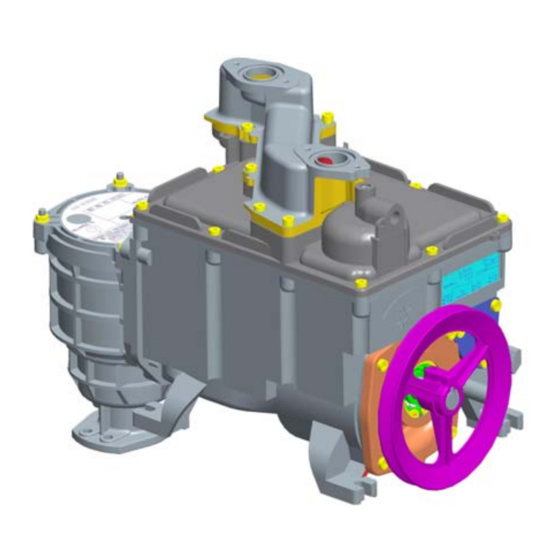
Qmax 80 l/min IMPORTANT NOTE When reporting a case of anomaly or malfunction, the name TQP-HS must be reported together with the serial number indicated on the type plate near the pump pulley (see above diagram). Please complete the problem report form in section 4.8 before contacting Tokheim. -
Page 15: Tqp-Hs 130 L/Min
³ 130 l/min 130 l/min TQP-HS TQP-HS IMPORTANT NOTE Do not install TQP-HS pumps, 80 or 130 lpm, in series on the same suction line. Separate suction lines are required as shown above. Page 2-3 Document Ref 942005-001 Rev 2.2... -
Page 16: Technical Characteristics
Flow rate: 40 and 80 l/min (motor of 1 kW) or 130 l/min (motor of 1.5 kW) 1.7 ≤ P ≤ 3.5 bar for TQP-HS 80 l/min Pressure: 2.3 ≤ P ≤ 3.5 bar for TQP-HS 130 l/min Suction capacity:... -
Page 17: Alignment Of The Pump
Sea level up to 2000 m Alignment of the Pump When installing the TQP-HS the following measures have to be taken into consideration regarding the V-belt. Adjust the pulleys of the motor and pump in such a way that they are positioned in one plane. -
Page 18: Schematic Diagram Of Operating Principles
TQP-HS for Fuel Dispensers Component Technical Manual Schematic Diagram of Operating Principles SCHEMATIC DIAGRAM REFERENCES Inlet pipe 15) Outlet valve reference to atmosphere Foot valve 16) By-pass Filter 17) Vortex centrifugal inlet Gear pump 18) Air separation channel Drain 19) High-pressure chamber... -
Page 19: Operating Description
2.6.2 ABOVE GROUND TANK APPLICATIONS The Tokheim suction pumps have been specifically designed to work in conjunction with underground tanks where the fuel level inside varies between 0.5 and 4 meters below the pump shaft.On suction pumps, minimal vacuum held on the suction line must be greater than 80mB to allow normal operation of pump and air elimination device. -
Page 20: Outlet Valve
TQP-HS for Fuel Dispensers Component Technical Manual The vortex body exists of two valves in parallel:- • The vortex regulating valve [12] A piston spring loaded valve which gives a constant headloss between the air separation channel and the recovery chamber. This valve stays open to keep the air separation system working at any pressure or flow. -
Page 21: Draining The Tqp-Hs
12mm. 2.6.7 DRAINING THE TQP-HS The TQP-HS is provided with a double drain [5] located at the lowest point of the housing. The pump can easily be drained without spillage by carrying out the following actions:- •... - Page 22 TQP-HS for Fuel Dispensers Component Technical Manual This page is intentionally blank Page 2-10 Document Ref 942005-001 Rev 2.2...
- Page 23 Component Technical Manual TQP-HS for Fuel Dispensers CONTENTS FAILURE DIAGNOSIS ....................3-2 Failure Diagnosis ....................3-3 Flow Charts ......................3-4 3.2.1 No Fuel Flow ..................3-4 3.2.2 Reduced Fuel Flow ................3-5 3.2.3 Uneven Fuel Flow................3-6 3.2.4 Closing of the Overflow Valve ............3-7 3.2.5...
-
Page 24: Failure Diagnosis
• Wear appropriate Personal Protective Clothing. 2) When the TQP-HS is stopped, ensure that the pumping unit is not pressurised due to the closing of the vent float valve. If there is no air coming from the air vent when the filterbox cover is removed, the vent float is closed and the pump is pressurised. - Page 25 Component Technical Manual TQP-HS for Fuel Dispensers Failure Diagnosis Prior to performing fault diagnosis/search, check the condition of the belt drives. Following any repair action to the pumping unit, ensure that all the necessary procedures required by Weights & Measures and applicable safety legislation are correctly followed.
-
Page 26: Flow Charts
TQP-HS for Fuel Dispensers Component Technical Manual Flow Charts 3.2.1 NO FUEL FLOW NO FUEL FLOW Check powe r Is the p ump su pply and run nin g? (direction co ndition of belt of r ota tion) drive Is the p ump... -
Page 27: Reduced Fuel Flow
Component Technical Manual TQP-HS for Fuel Dispensers 3.2.2 REDUCED FUEL FLOW REDUCED FUEL FLOW Has the drive belt s la ckened? R eplace the be lt Chec k co ndition of filte rs (h ose, PAS) Adjust the bypass (refer to section 4 .1 ) -
Page 28: Uneven Fuel Flow
TQP-HS for Fuel Dispensers Component Technical Manual 3.2.3 UNEVEN FUEL FLOW UNEVEN (PULSING) FUEL FLOW Ou tlet pr ess ure >1.5 bar? (refer to s ection 4.1) Is pres sure co nstant a fter outlet valve? Ma lfunctioning ups tream of PAS. Che ck elec tro -va lv e etc. -
Page 29: Closing Of The Overflow Valve
Component Technical Manual TQP-HS for Fuel Dispensers 3.2.4 CLOSING OF THE OVERFLOW VALVE CLOSING OF THE OVERFLOW VALVE Station ta nk ab ove pump level or su ction heigh t <1m Install an ti-syphon v alve or sp rin g o n foot-v alve C onsu lt H yd raulic Dept. -
Page 30: Excessive Noise
TQP-HS for Fuel Dispensers Component Technical Manual 3.2.5 EXCESSIVE NOISE EXCESSIVE NOISE Has the belt drive slac ken ed? Replac e belt N oise inside pump? Ou tlet pr essure >2.5 bar in bypa ss mode (refer to se ction 4 .1 ) Pressure a djustment (refer to section 4.1) - Page 31 Internal Air Entry in the Pump ................4-4 External Problems up-stream the TQP-HS ............4-4 Excessive Head Loss ................... 4-4 Air Entry on the pipework to the Storage Tank ........... 4-5 Problem Report form for the TQP-HS pump ............4-6 Page 4-1 Document Ref 942005-001 Rev 2...
-
Page 32: Troubleshooting
TROUBLESHOOTING Outlet Pressure The flow of the TQP-HS is regulated with the outlet pressure. To adjust the outlet pressure:- 1) Unscrew the pressure plug (item [20] in the schematic diagram). 2) Connect the pressure gauge via the flexible pipe into the hole of the outlet-cover (refer to section 5.3 for specific tools). -
Page 33: Inlet Pressure
Component Technical Manual TQP-HS for Fuel Dispensers Inlet Pressure The inlet pressure can be measured using a special filter box cover (refer to section 5.3 for specific tools) and a pressure gauge with range -1 bar up to 3 bar. -
Page 34: Internal Air Entry In The Pump
The float assembly is blocked in an open position, incorrectly installed or contains loose particles in between. External Problems up-stream the TQP-HS To test for problems up-stream the TQP-HS pumping unit:- • Check the operation of a non-return valve (where fitted). If the valve is defective (if mounted according to dispenser model), replace the valve. -
Page 35: Air Entry On The Pipework To The Storage Tank
(contact Tokheim Hydraulic Department for further advice). A defective foot valve can be detected by delivering about 20 litres with each pump and observing if the delivery is immediately starting when the motor starts and stays constant. -
Page 36: Problem Report Form For The Tqp-Hs Pump
TQP-HS for Fuel Dispensers Component Technical Manual Problem Report form for the TQP-HS pump Issued by: Report Date: Station Nam e: Meter Reading 1: City: Meter Reading 2: Country: Ground Pipework: TQ P-HS no.: -Length Installation Date: -Height Kind of Fuel:... - Page 37 Component Technical Manual TQP-HS for Fuel Dispensers CONTENTS SPARE PARTS AND MAINTENANCE TOOLS ............ 5-2 Exploded Views and Parts Lists ................5-2 5.1.1 Front View ................... 5-2 5.1.2 Back View ................... 5-4 5.1.3 Top View and Filterbox ................ 5-6 Frequently Used Spare Parts ................5-10 References to Specific Tools ................
-
Page 38: Spare Parts And Maintenance Tools
SPARE PARTS AND MAINTENANCE TOOLS Exploded Views and Parts Lists 5.1.1 FRONT VIEW... - Page 39 FRONT VIEW PARTS LIST Item No Description Désignation Français Part No Comments Nut Hex Self Lock M6 Ecrou Bride Autobloquant M6 900013-003 Screw HSS Cup Point M6x10 Vis HCCU M6x10 900019-001 Ring Retain Bore D50 Anneau Elast Int D50 900049-002 O-Ring 105,00x3,50 Joint Torique 105,00x3,50 900050-023...
-
Page 40: Back View
5.1.2 BACK VIEW OUTLET VORTEX BYPASS... - Page 41 BACK VIEW PARTS LIST Item No Description Désignation Français Part No Comments Washer Pl M10 Rondelle Pl M10 900008-014 O-Ring 6,00x2,30 Joint Torique 6,00x2,30 900050-020 O-Ring 35,00x3,00 Joint Torique 35,00x3,00 900050-024 O-Ring 38x3 Joint Torique 38x3 900050-109 Low Temperature only O-Ring 46,00x3,00 Joint Torique 46,00x3,00 900050-026...
-
Page 42: Top View And Filterbox
5.1.3 TOP VIEW AND FILTERBOX... - Page 43 TOP VIEW & FILTERBOX PARTS LIST Item No Description Désignation Français Part No Comments Screw HSHC M6x55 Vis CHC M6x55 900017-040 O-Ring 8,00x2,00 Joint Torique 8,00x2,00 900050-021 O-Ring 14,00x2,00 Joint Torique 14,00x2,00 900050-022 O-Ring 82,14x3,53 Joint Torique 82,14x3,53 900050-025 O-Ring 120,00x4,00 Joint Torique 120,00x4,00 900050-027 O-Ring 120,00x4,00 LT...
- Page 44 5.1.3 TOP VIEW (CONT.)
- Page 45 TOP VIEW PARTS LIST (CONT.) Item No Description Désignation Français Part No Comments Drain Screw Flat Seal Joint Plat vis de Purge 902394 Meter Support Cover Seal Joint Liaison Mesureurs 902396 Filterbox Boite de Filtre 902398 Footvalve Filterbox Clapet Filterbox 943260 Cover Meter Support PAS Couvercle Liaison Mesureurs...
-
Page 46: Frequently Used Spare Parts
TQP-HS for Fuel Dispensers Component Technical Manual Frequently Used Spare Parts Reference Description 902373 Pump pulley SPA 150 901321-002 Key A6 x 6 x 30 for motor and pump pulleys 900050-027 O-ring Viton Ø 4 x 120 for filter box cover 900050-002 O-ring Viton Ø... -
Page 47: Maintenance Kits
Component Technical Manual TQP-HS for Fuel Dispensers Maintenance Kits Gear Repair kit Contains a shaft + ball bearing (already assembled), a retaining ring, lip seal and O-ring. Order Number : 902298 Air Vent Repair kit Contains a gland nut + valve housing +... - Page 48 TQP-HS for Fuel Dispensers Component Technical Manual Outlet Valve Repair kit Contains an outlet valve assembly + spring + O-ring cover. Order Number : 902301 Vortex Repair kit Contains a valve tube + valves + springs + vortex body + O-ring (already assembled), seal vortex valve front-side and seal vortex rear-side.
- Page 49 Component Technical Manual TQP-HS for Fuel Dispensers This page is intentionally blank Document Ref 942005-001 Rev 2...
- Page 50 For Technical manual enquiries, contact: author@dundee.tokheim.com...
Need help?
Do you have a question about the TQP-HS and is the answer not in the manual?
Questions and answers