Advertisement
Quick Links
OPS243-A User Manual
UM-003
OmniPreSense OPS243-A short range radar sensor has an easy to use API to control the output of the
sensor. Simple commands can be used to configure the operation and output information provided by
the sensor. Default settings are noted below. Upon powering on the module, the default settings are
used.
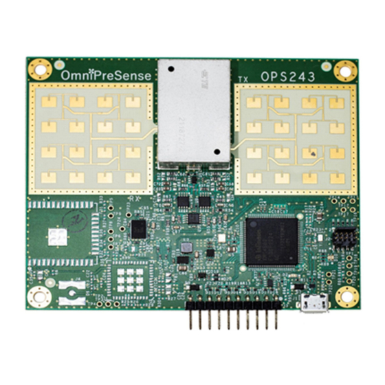
Installation Instructions
The OPS243-A provides a complete radar module on a single board. The coverage area or field of view
(FOV) for the OPS243-A is 20 in the azimuth (horizontal) and 24 elevation (vertical). Install the OPS243-
A facing the direction of the FOV to be covered. The antenna gain for the radar sensor is 11dBi.
Figure 1. OPS243-A Beamwidth
The OPS243-A can generally can be placed behind most any material (plastic, glass, wood, etc.) depending
on thickness. Typical applications will use plastics such as ABS or PVC at 3 or 6mm thickness. Some
materials will block the signal and the OPS243-A should not be placed behind these. Examples of these
are metal, concrete or brick.
UM-003-A OPS243-A User Manual
1
OmniPreSense Corporation
Advertisement

Subscribe to Our Youtube Channel
Related Manuals for OmniPreSense OPS243-A

Summary of Contents for OmniPreSense OPS243-A
- Page 1 OPS243-A User Manual UM-003 OmniPreSense OPS243-A short range radar sensor has an easy to use API to control the output of the sensor. Simple commands can be used to configure the operation and output information provided by the sensor. Default settings are noted below. Upon powering on the module, the default settings are used.
- Page 2 PC/Mac which can easily connect to a serial port and accept data over USB from the OmniPreSense module. To begin using the OmniPreSense sensor, first download Tera Term or PuTTY onto your PC/Mac. With the OmniPreSense sensor plugged into the USB port of your PC/Mac, start Tera Term or PuTTY. A configuration window such as Figure 2 or Figure 3 will appear.
- Page 3 A simple wave of the hand will show data like that shown in Figure 4. Any of the API commands can now be executed to change the output data or query the configuration. Figure 4. Streaming Data with Tera Term UM-003-A OPS243-A User Manual OmniPreSense Corporation...
- Page 4 Figure 5. Streaming Data with PuTTY UM-003-A OPS243-A User Manual OmniPreSense Corporation...
- Page 5 31.1 m/s (69.5 mph) while 20,000 (S2 command) provides up to 62.2 m/s (139.1 mph). The resolution of the reported speed increases as the sample frequency goes down. The range of values is summarized in Table 3. UM-003-A OPS243-A User Manual OmniPreSense Corporation...
- Page 6 69.5 0.061 0.136 20,000 62.2 139.1 0.121 0.272 50,000 155.4 347.7 0.304 0.679 100,000 310.8 695.4 0.608 1.358 * 1024 buffer size, 512 buffer size accuracy will be twice these values, 256 four times UM-003-A OPS243-A User Manual OmniPreSense Corporation...
- Page 7 Firmware Version/Board ID – returns current firmware version of the module. Firmware version consists of a major revision, minor revision, and patch revision in the form of xx.yy.zz. Command Name Value Firmware Version Number Read {"Version":"1.3.1"} Firmware Build Number Read {"Build":"20181005_1335"} Unique Board ID Read {"UID":"b2000040b7a12400d5188041"} UM-003-A OPS243-A User Manual OmniPreSense Corporation...
- Page 8 For example, setting to F2 will Decimal Places Write report 2 decimal places (ex. 10.35). F0 will provide the integer value only. Valid values of n are 0-5. Decimal Place Setting Read Query the number of decimal places set. UM-003-A OPS243-A User Manual OmniPreSense Corporation...
- Page 9 256 samples are collected before processing 2.50 2.30 256 Buffer 2.10 1.90 512 Buffer 1.70 1024 Buffer 1.50 1.30 1.10 0.90 0.70 0.50 0.30 0.10 -0.10 1,000 10,000 100,000 Sampling Rate Figure 6. Doppler (-A) Buffer Size versus Resolution UM-003-A OPS243-A User Manual OmniPreSense Corporation...
- Page 10 Writing ?F will provide the current transmitter output frequency. Command Name Value Frequency Setting Write T=0 is the default setting for 24.125GHz. ?F returns the output frequency of the Frequency Output Read transmitter in GHz. UM-003-A OPS243-A User Manual OmniPreSense Corporation...
- Page 11 Disable the lights with Oc. By default, the processing activity lights are disabled. Turns on output to format data in JSON format. An example would output: JSON Mode On Write {"speed":0.58, "direction":"inbound", “time”:105, :tick”:135}. Use Oj to turn off JSON mode. UM-003-A OPS243-A User Manual OmniPreSense Corporation...
- Page 12 BZ will report zero Blank Data Reporting Write value. BL will report blank lines. BS will report a space. BC will report with a comma. BT will report a timestamp. Use BV to turn off. UM-003-A OPS243-A User Manual OmniPreSense Corporation...
- Page 13 Figure 7 shows how filtering can allow detection for certain objects and mask out others. Command Name Value Object Detection Interrupt Write Turn object detection interrupt on. Use “Ig” to turn off. Figure 7. Speed, Range and Magnitude Filtering UM-003-A OPS243-A User Manual OmniPreSense Corporation...
- Page 14 Query Time Read Ex. {“Clock”:”50”} reports 50 seconds since power on. Set Time Write Reset the clock start time. For example, n = 10 will start the clock at 10 seconds and then continue counting. UM-003-A OPS243-A User Manual OmniPreSense Corporation...
- Page 15 “overdrive” of 0.2 dB when utilized. Turn transmit off and put in sensor in receive Transmit Off Write only mode. Use P! to turn transmit back on. System Reset Write Full system reset including the clock. UM-003-A OPS243-A User Manual OmniPreSense Corporation...
- Page 16 Set the amount of time to sleep between data processing. Ex., n = 5 would set the module to Set Sleep Time Write sleep for 5 seconds (RF powered off) between a transmit/receive pulse and processing. 0 ≤ n ≤ 4,294,967 UM-003-A OPS243-A User Manual OmniPreSense Corporation...
- Page 17 C) radar only. m<n High Range Magnitude Write n is any number upon which no detected Filter magnitudes above that number will be reported. m<0 resets to no limit. FMCW (-B, - C) radar only. UM-003-A OPS243-A User Manual OmniPreSense Corporation...
- Page 18 Upon power loss or recycling power, the saved configurations will be used as the default. Read Settings Write Read the current flash settings. Reset Flash Settings Write Will overwrite current saved settings and return to the factory default settings. UM-003-A OPS243-A User Manual OmniPreSense Corporation...
- Page 19 L'exploitation est autorisée aux deux conditions suivantes: (1) l'appareil ne doit pas produire de brouillage, et (2) l'utilisateur de l'appareil doit accepter tout brouillage radio électrique subi, même si le brouillage est susceptible d'en comprom-ettre le fonctionnement. UM-003-A OPS243-A User Manual OmniPreSense Corporation...
- Page 20 Non-modification Statement OmniPreSense Corporation has not approved any changes or modifications to this device by the user. The antenna design is intended to be used as is with no modifications. Any changes or modifications could void the user’s authority to operate the equipment.
- Page 21 Transmit Power • Duty Cycle Control • Debug Modes • UART Interface • Maximum Speed • Motion Interrupt • Min/Max Magnitude Filter • Watchdog Timer • Persistent Memory • System Reset • Simple Counter UM-003-A OPS243-A User Manual OmniPreSense Corporation...
- Page 22 Revision History Version Date Description November 14, 2019 Initial release. UM-003-A OPS243-A User Manual OmniPreSense Corporation...
Need help?
Do you have a question about the OPS243-A and is the answer not in the manual?
Questions and answers