Table of Contents
Advertisement
Available languages
Available languages
FEDERAL SIGN AL
VAM A
SIRENA ELECTRONICA
ELECTRONIC SIREN
ELEKTRONISCHE SIRENE
AS- 422
MANUAL DE INSTALACIÓN E INSTRUCCIONES DE
FUNCIONAMIENTO
INSTALLATION AND OPERATING INSTRUCTIONS
MONTAGE-UND BEDIENUNGSANLEITUNG
FEDERAL SIGNAL VAMA-C/Dr.Ferrán,7 (08339)VILASSAR DE DALT SPAIN-Tel:34 3 741 79 00 -Telefax:343 753.03.62
Advertisement
Table of Contents

Summary of Contents for Federal Signal VAMA AS-422
- Page 1 FEDERAL SIGN AL VAM A SIRENA ELECTRONICA ELECTRONIC SIREN ELEKTRONISCHE SIRENE AS- 422 MANUAL DE INSTALACIÓN E INSTRUCCIONES DE FUNCIONAMIENTO INSTALLATION AND OPERATING INSTRUCTIONS MONTAGE-UND BEDIENUNGSANLEITUNG FEDERAL SIGNAL VAMA-C/Dr.Ferrán,7 (08339)VILASSAR DE DALT SPAIN-Tel:34 3 741 79 00 -Telefax:343 753.03.62...
-
Page 2: Descripcion General
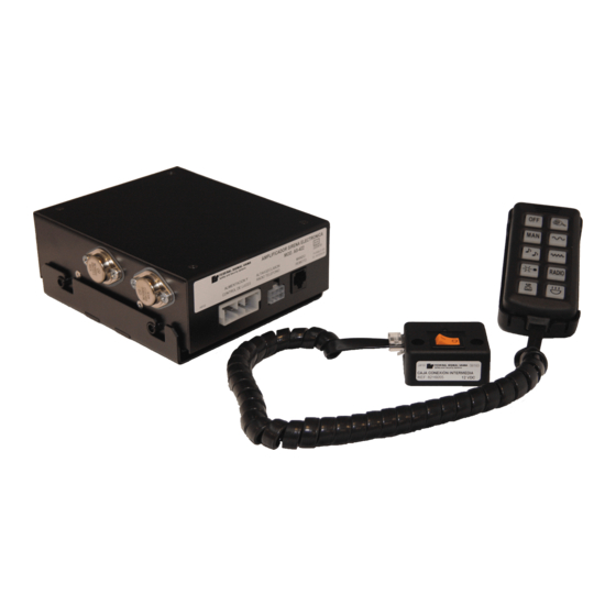
DESCRIPCION GENERAL La sirena electrónica AS-422 es una moderna sirena de mando remoto con funciones de megafonía que también incluye dos teclas para controlar dos sistemas de luces de señalización. Se puede considerar que el equipo consta de tres partes; amplificador, módulo de control y caja de conexionado. - Page 3 Conectar las cables de alimentación directamente a batería o a una buena toma próxima a ella. Proteger la instalación con cuatro fusibles de 15 amperios situado lo más cerca posible de la conexión a batería de acuerdo con los diagramas de conexionado que aparecen al final de este manual.
- Page 4 - Si se taladra la estructura del vehículo, asegurarse de que a ambos lados no hay nada que pueda ser dañado. REVISION DEL CONTENIDO Dentro de la caja de la sirena electrónica AS-422 se deberá encontrar: 1 Este manual de instalación y funcionamiento. 1 Amplificador sirena electrónico AS-422. 1 Base soporte amplificador.
- Page 5 Un destornillador Philips PH 3 Una llave fija nº 7 Una llave allen 3 mm. 4 portafusibles 4 fusibles de 15 A Opcionalmente puede necesitar además: Un relé de automóvil (si instala la conmutación automática de mando por claxon) Terminales faston para relé de automóvil. Dos terminales Electro Tap (AMP) azules ( si se realiza la conexión a radioteléfono) Para instalación en motocicleta, se recomienda el uso de un pulsador de mando (Pulsador Vama, ref.: 9014056)
- Page 6 Con una broca de 3 mm. se efectuarán los taladros y se fijará el pie articulado al vehículo con los 3 tornillos autoroscantes 4,2x16. Finalmente se atornillará el pie articulado con la base del módulo de control con los 4 tornillos M4x12 de cabeza avellanada, arandelas de presión M4 y tuercas M4 Una vez fijadas la base del módulo de control , ya se podrá...
- Page 7 (pag.49) En la Fig.14, , se muestra una posible ubicación del amplificador en una motocicleta. CONEXIONADO ELECTRICO El conexionado eléctrico se realizará según el esquema de conexionado que aparece en la pag. 11: Esquema de conexionado 1 Normalmente el amplificador se suministra con los puentes internos colocados en la posición "no detección fallo luces".
- Page 8 equipo, el pulsador del claxon deja de controlar el claxon del vehículo y pasa a controlar la conexión especial de la sirena. El claxon vuelve a su estado normal cuando se desconecta la sirena. B) Instalar un conmutador que permita hacer manualmente la operación anterior. Para instalar el relé...
-
Page 9: Instrucciones De Funcionamiento
El cable ROSA (FALLO LAMPARAS), se conectará en aquellos puentes cuyas luces prioritarias sean focos estroboscópicos controlados por una Fuente de alimentación 188/6S con salida de detección de fallo de lámparas. COMPROBACION DESPUES DE LA INSTALACION Para comprobar el correcto funcionamiento del equipo una vez instalado, conectar el Interruptor general de la caja intermedia (posición “I”). - Page 10 M E G A F O N I A El micrófono del sistema de megafonía, se encuentra en el interior del módulo de control, pudiéndose distinguir a través de las ranuras situadas en la parte superior del módulo de control. Para usar la megafonía, se extraerá el modulo de su base y bastará con pulsar esta tecla y hablar dirigiendo la voz hacia el micrófono.
- Page 11 REPRODUCCION RADIOTELEFONO Al pulsar esta tecla, las comunicaciones recibidas por el radioteléfono se amplifican reproducen a través del altavoz de la sirena. MANDOS DE LUCES LUCES PRIORITARIAS Esta tecla activa las "LUCES PRIORITARIAS" que se han conectado a los dos cables de color BLANCO.
- Page 13 El amplificador de la sirena AS-422 tiene dos tipos de detectores para realizar esta función según, las luces prioritarias sean rotativas o estroboscópicas.
-
Page 17: General Description
GENERAL DESCRIPTION The AS-422 electronic siren is a modern remote controlled siren with public address functions, which also includes two keys to control two light systems. The equipment can be said to consist of three sections: amplifier, control head and connection box. -
Page 18: Specifications
Connect the power cables directly to the battery or a chassis part that will provide an effective ground path. Protect the installation with four 15 A fuses situated as close as possible to the battery connection, as shown in the wiring diagrams at the end of this manual. The lights or warning lightbars are supplied with a wiring diagram. -
Page 19: Package Contents
-When drilling into a vehicle structure, be sure that both sides of the surface are clear of anything (brake lines, electrical wiring...) that could be damaged. PACKAGE CONTENTS Inside the AS-422 electronic siren box you should find: 1 This installation and operating manual 1 AS-422 electronic siren amplifier... - Page 20 A no. 7 fixed spanner 4 fuseholders 4 15 A fuses Optionally, you may also need: One automobile relay (if the automatic switch-over for horn control is installed) Faston terminals for automobile relay Two blue Electro Tap (AMP) terminals (if connecting to a radiotelephone) For motorbike installations, we recommend using a control button (Vama button, ref: 9014056) INSTALLATION OF THE CONTROL HEAD AND THE CONNECTION BOX...
- Page 21 B) INSTALLING THE CONNECTION BOX Choose a suitable site for the connection box. This could be on the lower righthand side of the vehicle’s central console, as shown in Figure 9. (For motorbike mounting, the connection box should be installed in a position protected from water). The box is positioned so that the red potentiometer (volume adjustment) faces the inside of the vehicle (see Fig.9, Page.
- Page 22 If you decide to use the lamp failure detection system, see APPENDIX 1. (Page.26) The following will be noted in wiring diagram 1: WARNING: Red wires: + 12 V BATTERY Brown wire: NEGATIVE BATTERY DO NOT INVERT POLARITY!! Protect the installation with four 15 A fuses, placing one in each of the red wires as close as possible to the battery connection.
-
Page 23: Checking After Installation
CONNECTION OF THE HORN CONTROL, (see Fig.15, Page.49) In MOTORBIKES, the siren can be controlled through a waterproof manual button which is independent of the horn (See in OPERATING INSTRUCTIONS “SIREN CONTROL BY HORN OR BUTTON (motorbikes)”). For the above, connect the button to the “GREEN” wire leading from the 6-way minifit connector (pin 2) of the amplifier. - Page 24 If the horn connection has been made with a relay, verify its operation as follows: -Turn off the main switch in the intermediate box (position “0”). Check that the vehicle horn functions normally. -Turn on the main switch in the intermediate box (position “I”). Press the horn button once. The same siren sound should be produced as when pressing “MAN”...
-
Page 25: Auxiliary Lights
TWO TONES The sound corresponding to this key is a succession of two tones with different frequencies. The “MAIN WARNING LIGHTS” are activated too. DAY/NIGHT This key offers the posibility of two levels of sound intensity. RADIOTELEPHONE On pressing this key, the communication received by the radiotelephone are amplified and reproduced through the siren's speaker. - Page 27 In these countries the amplifier will be configured according to the type and number of warning lights used. The AS-422 siren amplifier has two types of detectors for this purpose, depending on whether the main warning lights are rotating or strobe lights.
-
Page 31: Allgemeine Beschreibung
ALLGEMEINE BESCHREIBUNG Bei der elektronischen Sirene AS-422 handelt es sich um eine moderne, ferngesteuerte Sirene mit Lautsprecherfunktionen, die darüberhinaus über zwei Schalter zur Steuerung von zwei Lichtsystemen verfügt. Die Anlage besteht aus drei Bereichen: Verstärker, Steuerelement und Anschlußbox. Der Verstärker besteht aus einem Metallgehäuse, das die elektronischen Schaltklreise des Verstärkers, den Tongenerator sowie zwei Relais für die Signalsteuerung enthält. -
Page 32: Sicherheitshinweise Für Den Monteur
Wurde die Polarität vertauscht, ist die Sicherung F1 (15A) im Verstärker zu ersetzen Seite.45 BAUTEILE-ANORDNUNG). Schließen Sie die Stromkabel direkt an die Batterie oder einen Teil des Chassis an der eine wirksame Erdung liefert. Schützen Sie die Anlage mit vier 15 A. Sicherungen, die so nah wie möglich an der Batterie installiert sein sollten;... - Page 33 Montagefläche frei von Teilen sind, die bei diesem Vorgang Schaden nehmen könnten. P A C K U N G S I N H A L T Innerhalb des Kartons der Elektroniksirene AS-422 finden Sie: 1 Diese Montage- und Bedienungsanleitung 1 AS-422 Elektroniksirenen-Verstärker 1 Verstärker-Halterung...
- Page 34 Einen Philips PH 3 Schraubenzieher Einen Schraubenschlüssen Nr.7 15A Sicherungen Darüberhinaus benötigen Sie eventuell noch: Ein KFZ-Relais (falls die automatische Umschaltung für die Hupensteuerung installiert wird). Schnellkupplungen für KFZ-Relais. Zwei blaue Electro Tap (AMP) Klemmleisten (falls Anschluß an ein Funktelefon). Für Motorrad-Montage empfehlen wir die Verwendung eines Schalterknopfes (Vama-Knopf, ref: 9014056).
-
Page 35: Einbau Des Verstärkers
Schlleßlich wird das Schwenk-Unterteil am Steuerelement-Unterteil mit den 4 Flachkopfschrauben M4x12, den M4 Druckscheiben und M4 Muttern befestigt. Nach Positionierung des Steuerelement-Unterteils kann das Steuerelement auf dem Unterteil montiert werden. EINBAU ANSCHLUSSBOX Wählen Sie eine geeignete Position für die Anschlußbox. Dies könnte unten rechts an der Mittelkonsole des Fahrzeugs wie in Abb. - Page 36 Abb. 14, (Seite.49) : zeigt einen möglichen Montagepunkt für den Verstärker bein einem Motorrad. V E R K A B E L U N G Die Verdrahtung erfolgt entsprechend dem Schaltbild auf Seite 40: “Schaltbild 1”. Der Verstärker wird ab Werk mit der Einstellung der Brücken auf der Position “keine Leuchten-Fehlermeldung”...
- Page 37 unterbrochen wird. B) Bauen Sie einen Schalter ein, mit dem der vorstehend geschilderte Betrieb manuell geschaltet werden kann. Um das Relais oder den Schalter einzubauen, gehen Sie wie folgt vor: - Suchen Sie das Kabel, das die Fahrzeughupentaste mit der Hupe oder mit dem Relais verbindet, welches die Hupe steuert.
- Page 38 bestimmte Vorsichtsmaßnahmen zu treffen. Hohe Schalldrücke können das menschliche Hörvermögen beeinträchtigen; stellen Sie sich daher in einiger Entfernung vom Lautsprecher auf und testen Sie die Sirene vorzugsweise im Freien. Drücken Sie MAN. Es wird ein Sirenenton erzeugt, der bis zum maximalen Ton anschwillt und dann nachläßt, bis der Ton ganz aufhört.
- Page 39 Die Lautstärke kann mit Hilfe des Potentiometers an dem roten Stellrad eingestellt werden, das sich in der ANSCHLUSSBOX befindet. Wird das typische Rückkopplungs-Pfeifen erzeugt, drehen Sie die Lautstärke herunter, bis es nicht mehr zu hören ist. Ist die Lautstärke korrekt eingestellt, sind keine weiteren Einstellungen erforderlich.
- Page 40 Z U S A T Z L E U C H T E N Diese Taste aktiviert die “ZUSATZLEUCHTEN”, die an das GRÜNE Kabel angeschlossen sind (s. Schaltbilder). SIRENENSTEUERUNG ÜBER HUPE ODER SCHALTER (Motorräder) Die Sirenensteuerungsfunktionen bleiben unverändert, wenn die Steuerung über die Hupe (Kraftfahrzeuge) oder bei Motorrädern über einen wassergeschützten Handschalter, der unabhängig von der Hupe ist (ref.: Vama:9014056), erfolgt: - Einmaliges Drücken erzeugt den gleichen Sirenenton wie Drücken...
- Page 42 Fahrer den Ausfall einer der Warnleuchten melden. In diesen Ländern wird der Verstärker entsprechend dem Typ und der Anzahl der verwendeten Warnleuchten konfiguriert. Der AS-422 Sirenenverstärker verfügt zu diesem Zweck über zwei Detektoren, je nachdem, ob die Hauptwarnleuchten order Stroboskopleuchten eingesetzt werden.
- Page 46 SITUACIÓN DE COMPONENTES SIRENA AS-422 COMPONENTS LAYOUT / ELECTRONIC SIREN AS-422 BAUTEIL - ANORDNUNG / ELEKTRONISCHE SIRENE AS-422 PUENTE " J P 2 " PUENTE " J P 1 " PUENTE " J P 3 " VOLUMEN R A D I O...
- Page 47 MODULO DE CONTROL SIRENA ELECTRÓNICA AS-422 Figura 0 : CONTROL HEAD ELECTRONIC SIREN AS-422 STEUERELEMENT Figure 0 : ELEKTRONISCHE SIRENE AS-422 Abb 0 : Nº PUBLIC ADDRESS VOLUME CONTROL LAUTSPRECHER-LAUTSTÄRKENREGLER TO AMPLIFIER ZUM VERSTÄRKER CONNECTION BOX ANSCHLUBBOX DAY/NIGHT TAG/NACHT TWO TONES...
- Page 48 Figura 4: Vista del pulsador manual (ref. Vama: 9014056 ) instalado en una motocicleta. Figura 5: Vista del pie articulado Figure 4: View of the manual button (ref. Vama: igure 5: View of hinged base 9014056) installed on a motorbike. Abb 5: Das Schwenk-Unterteil Abb 4: Manuell-schalter (ref.
- Page 49 Figura 10: Vista módulo de control acoplado con su base y conectado a la caja de conexionado. Figura 9: Ubicación caja de conexionado Figure 10: View of the control head fitted into its base Figure 9: Connection box location and connected to the connection box. Abb 9: Anschlußbox-position.
- Page 50 Fig. 14: Instalación del amplificador debajo del asiento de una motocicleta. Fig. 14: Installing the amplifier underneath the seat of a motorbike. Abb 14: Einbau des verstärkers unterhalb des motorradsitzes. CONEXIONADO DEL MANDO POR CLAXON Figura 15 : CONNECTION OF THE HORN CONTROL Figure 15 : Abb 15 : ANSCHLUSS...
Need help?
Do you have a question about the AS-422 and is the answer not in the manual?
Questions and answers