Table of Contents
Advertisement
Quick Links
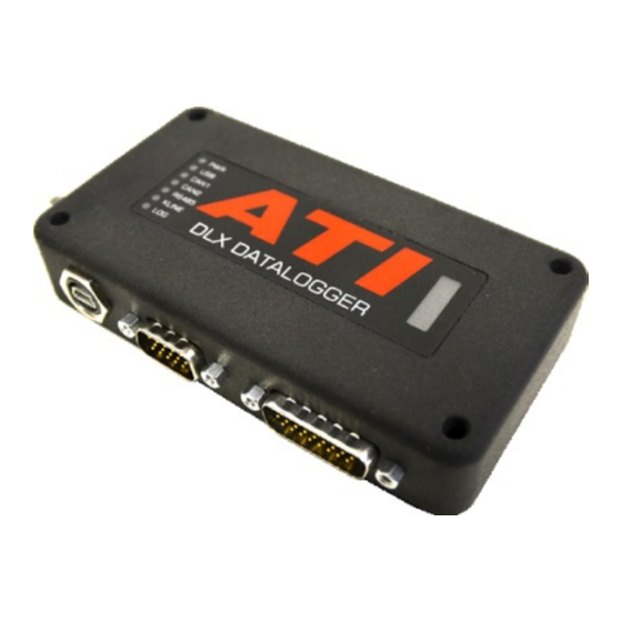
DLX Datalogger
1100 Series
Quick Start Guide
The DLX Datalogger offers a unique combination of functions that provide the
features of a CAN interface, data acquisition module, and data logger all in one compact package. Different variations of
the DLX are available. Additional channels are available depending upon the unit purchased. The standard DLX hardware
provides the following:
•
Four 0 to 20 V single-ended analog inputs
•
Four +/- 5 V differential analog inputs
Four K-type thermocouple inputs
•
Four digital input/output channels
•
•
One 5 to 15 V sensor power output
Connecting the DLX
The DLX uses two D-Sub connections to handle all the sensor inputs, network communication and DC power during data
acquisition and stand-alone data-logging. Connect to the PC using the USB cable to to configure the DLX and retreive MDF4
data-log files. The wire diagram below shows the functions of break-out cables available for the DLX:
Note: The DLX can be powered by USB cable or by COM cable using an external power supply/vehicle battery.
Public
DOC-000078
•
One ISO9141 K-Line channel
•
Two high speed CAN 2.0B channels
Removable SDHC memory card
•
ASAM MDF4 file format
•
1
Advertisement
Table of Contents

Summary of Contents for ATI Technologies DLX 1100 Series
- Page 1 DLX Datalogger 1100 Series Quick Start Guide The DLX Datalogger offers a unique combination of functions that provide the features of a CAN interface, data acquisition module, and data logger all in one compact package. Different variations of the DLX are available. Additional channels are available depending upon the unit purchased. The standard DLX hardware provides the following: •...
- Page 2 Connectivity - I/O Cable Part Number: 150-0211-6FT (DB26 to un-terminated cables plus 4x K-type connectors) Public DOC-000078...
- Page 3 Connectivity - COM Cable Part Number: 150-0210-6FT (DB15 to un-terminated cables plus 2x DB9 connectors) Adding DLX to the VISION Device Tree The DLX Datalogger must be added to the device tree in the VISION project window. The device tree describes the physical configuration and communication protocols of all associated hardware devices and connections.
- Page 4 Power up the devices and press the Online icon in the project toolbar (or press F4) to enable communication. Building the device tree: DLX Datalogger in the device tree: Note: Refer to the VISION User Manual for more information on adding hardware to the VISION Device tree. DLX LED Status Lights The DLX has seven status lights that display the DLX states by blinking, staying solid and changing colors based on the function being performed, connectivity status or errors that may occur.
- Page 5 DLX Specification +5/-5 V Analog Inputs Number of Channels (4) bipolar differential inputs Input Range ±5 V ADC Resolution 16-bits Max Sample Rate 2 KHz per channel, fixed Input Impedance 20 MΩ Input Protection ± 36 V 0-20 V Analog Inputs Number of Channels (4) unipolar single-ended inputs* Input Range...
- Page 6 Communications USB PC Communications (1) USB 2.0 channel; supporting VISION and third party software via XCP CAN Network Communication (2) CAN 2.0B channels K-Line Network (1) ISO 9141 compliant K-Line channel Communication (2) Version 2.1 channels; supporting master and slave mode* Operating Conditions (1) Power, (1) USB communication, (2) CAN communication, (1) K-Line Bi-colour LED Indicators...
- Page 7 ATI Global Offices and Contact Details Worldwide Offices United States sales_us@accuratetechnologies.com Japan sales_jp@accuratetechnologies.com support_us@accuratetechnologies.com support_jp@accuratetechnologies.com +1 248-848-9200 +81 3-5325-6222 China sales_cn@accuratetechnologies.com Sweden sales_se@accuratetechnologies.com support_cn@accuratetechnologies.com support_se@accuratetechnologies.com +86-138-1023-6357 +46 (0) 31-773-7140 France sales_fr@accuratetechnologies.com United Kingdom sales_uk@accuratetechnologies.com support_fr@accuratetechnologies.com support_uk@accuratetechnologies.com +33 (0) 1 72 76 26 10 +44 (0) 1767-652-340 Germany sales_de@accuratetechnologies.com...
Need help?
Do you have a question about the DLX 1100 Series and is the answer not in the manual?
Questions and answers