
Related Manuals for FTS G6-DB

Summary of Contents for FTS G6-DB
- Page 1 EXTREME ENVIRONMENTS. EXTREMELY SIMPLE. G6-DB Satellite Data Transmitter Operator’s Manual 1.800.548.4264 | www.ftsinc.com 700-G6-DB-Man Rev1 12 Feb 2021...
- Page 2 Contact Information Canadian Headquarters: 1065 Henry Eng Place Victoria, BC | V9B 6B2 | Canada www.ftsinc.com Toll-free: 1.800.548.4264 Local: 250.478.5561 Technical support portal: http://support.ftsinc.com Email: service@ftsinc.com Warranty Terms and Conditions https://ftsinc.com/support/warranty/...
-
Page 3: Table Of Contents
4.3.3 POWER SUPPLY ............................. 10 TRANSMISSION ANTENNA ............................ 10 4.4.1 Directional Antenna............................. 10 4.4.2 EON2 Omnidirectional Antenna ......................11 COMMUNICATING WITH THE G6-DB ......................... 12 5.1.1 RS-232 Port ..............................12 5.1.2 USB Port ................................12 5.1.3 Serial interface ............................... 12 Connecting the Equipment .......................... - Page 4 NOAA / EUMETSAT TRANSMIT PARAMETERS ....................16 ADDITIONAL TRANSMIT PARAMETERS ......................18 5.7.1 Message Centering ............................19 SET RF POWER LEVELS ............................20 CONFIRMING GPS SYNCHRONIZATION ......................22 5.10 CONFIRM TIMED TRANSMISSION STATUS ....................... 23 5.11 FAILED TRANSMISSION ............................25 5.12 COMMON COMMANDS............................
- Page 5 6.3.15 Set Random Message Format ........................37 6.3.16 Enable or Disable Random Transmission Message Counter ............37 DATA BUFFER LOADING COMMANDS ......................37 6.4.1 Timed Transmission Message Buffer Read .................... 37 6.4.2 Load Timed Transmission Message Buffer .................... 38 6.4.3 Append to Self-timed Transmission Message Buffer (Ver 6.02 Firmware or Greater) ....
- Page 6 DCP GOES Transmit Frequencies – Standard Certificate 1.0 ..............52 DCP GOES Transmit Frequencies Standard Certificate 2.0................56...
-
Page 7: Handling
HANDLING AND SAFETY HANDLING Although G6-DB is rugged, it should be handled as a precision instrument, that is, with caution and attention. Before powering up the transmitter, ensure the antenna is properly connected in accordance with general guidance contained in Section 4.3... -
Page 8: Goes System
OVERVIEW The G6-DB is a satellite data transmitter that operates with the GOES (Version 2.0 - CS2) and METEOSAT networks. The transmitter has a global positioning system (GPS) that provides accurate location and time synchronization information. The G6-DB was designed to be used in Data Collection Platforms (DCPs), also called weather stations. -
Page 9: Data Retrieval
NOTE: It is only possible to use a GOES platform through approval and certification of the transmitter by NESDIS. GOES Satellite Antenna Equipped DCP with Ground Receiving GOES transmitter Station Figure 1: GOES system / DCP equipped with G6-DB 700-G6-DB- Man Rev. 1 dft5 11 Feb 2021 Page 3/65... -
Page 10: Acquiring Permission
3. Once logged in select “Submit an Application for a GOES DCS SUA”. 4. Complete and submit the application. More information about the GOES Data Collection System can be found on the NOAA site. 700-G6-DB- Man Rev. 1 dft5 11 Feb 2021 Page 4/65... - Page 11 ±20 Hz disciplined to GPS; After this process, a GPS fix occurs after power up and once per day. Channel Bandwidth 100 bps: 3 KHz GPS Receiver Type: 3.3 V active Connector: SMA jack 700-G6-DB- Man Rev. 1 dft5 11 Feb 2021 Page 5/65...
- Page 12 21.88 x 13.15 x 4.4 cm (8.61” x 5.17” x 1.7”) connectors: Weight: 955 g Interface command protocols Binary command protocol: Available on RS-232 ASCII command protocol: Available on all ports 700-G6-DB- Man Rev. 1 dft5 11 Feb 2021 Page 6/65...
-
Page 13: Field Site Requirements
INSTALLATION FIELD SITE REQUIREMENTS For proper operation of the G6-DB transmitter, the user must follow the following requirements: • Install the antenna so that it has a clear view of the sky (view of the satellite). • For directional antennas, the user must point it toward the satellite (Section 4.4.1). -
Page 14: Led Function
The LEDs may represent the following conditions: • When the G6-DB is powered for the first time, the four LEDs quickly light up in a circular motion representing an auto test sequence, and then the GPS LED will light up. -
Page 15: Reset Function
NOTE: If the transmitter cannot synchronize to UTC time during the first 20 minutes, the transmitter will switch off the GPS module for one minute and then will restart the synchronization cycle. This process continues until the transmitter successfully synchronizes to UTC time. 700-G6-DB- Man Rev. 1 dft5 11 Feb 2021 Page 9/65... -
Page 16: Rf Connectors
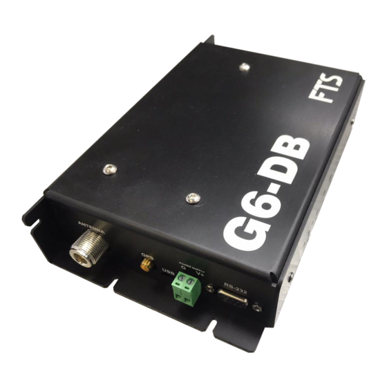
4.3.1 ANTENNA CONNECTOR The G6-DB uses the type N female connector for RF power out. It must have a proper connection before any transmission occurs. Failure to use a properly matched cable and connector may cause permanent damage to the equipment. The nominal impedance is 50 ohms; the frequency range is approximately 400 to 403 MHz. -
Page 17: Eon2 Omnidirectional Antenna
It requires no assembly and no aiming in most locations. It just needs to be mounted with a clear view of the sky., Additionally, the FTS EON2 antenna is dome-shaped for shedding snow and ice, is completely sealed for use in harsh environments, and has the option of an embedded GPS antenna. -
Page 18: Communicating With The G6-Db
CONFIGURING COMMUNICATING WITH THE G6-DB A method to communicate with the G6-DB transmitter must be established. There are two ways to communicate: Connecting the transmitter to a PC (RS-232 or USB port) and run a terminal emulation program such as Windows HyperTerminal. -
Page 19: Connecting The Equipment
Connect the cables as shown in Figure 6. Note that only one of either the USB cable or the communication serial cable may be required depending on the equipment in use. However, both can be used simultaneously. 700-G6-DB- Man Rev. 1 dft5 11 Feb 2021 Page 13/65... -
Page 20: Communication Protocols
IMPORTANT: Both serial ports can be used for ASCII command protocols, but for binary protocol commands only the serial communication RS-232 port will work 700-G6-DB- Man Rev. 1 dft5 11 Feb 2021 Page 14/65... -
Page 21: Command Access Level
The access level of each command is noted in the command descriptions in Chapter 6. Some commands are only available when transmissions are disabled. This is also noted along with each command description. 700-G6-DB- Man Rev. 1 dft5 11 Feb 2021 Page 15/65... -
Page 22: Configuration Format
CONFIGURATION FORMAT The G6-DB will arrive with the factory default settings and the transmitter configuration will be displayed in the following format: >RCFG NESID=0000 TCH=0 TBR=0 Mandatory parameters TIN=00:00:00:00 provided by NOAA FTT=00:00:00 TWL=0 CMSG=N EBM=N TPR=S TDF=A RCH=0 RBR=0... - Page 23 Table 1: NOAA Transmit parameters setting examples The transmitter will always return a “OK” message when the parameters above are entered correctly. Check the entered values if any parameter gives a different answer. 700-G6-DB- Man Rev. 1 dft5 11 Feb 2021 Page 17/65...
-
Page 24: Additional Transmit Parameters
>CMSG=Y Y=Yes (Recommended). N=No. See Section Center message CMSG=N >OK 9.7.1 for details. in window Y=Yes. The G6-DB transmitter will transmit even if there is no data in the transmit >EBM=Y buffer. EBM=N Empty buffer message N=No. There will be no transmission if there >OK... -
Page 25: Message Centering
700-G6-DB- Man Rev. 1 dft5 11 Feb 2021 Page 19/65... -
Page 26: Set Rf Power Levels
GOES Data Collection Platform Radio Set (DCPRS) CERTIFICATION STANDARDS, NOAA/NESDIS, June 2009; http://www.noaasis.noaa.gov/DCS/docs/DCPR_CS2_final_June09.pdf; Section 4.1.1 EUMETSAT International Data Collection System Users’ Guide, Edition 10 version 1, October 2009 https://www.eumetsat.int/website/home/Data/TechnicalDocuments/index.html 700-G6-DB- Man Rev. 1 dft5 11 Feb 2021 Page 20/65... - Page 27 NOTE: If the message returns BAD PARAMETER instead of OK, an error was made inputting the transmit parameters. Review the configuration and then re-enter the erroneous command with the correct parameter. 700-G6-DB- Man Rev. 1 dft5 11 Feb 2021 Page 21/65...
-
Page 28: Confirming Gps Synchronization
1) If a GPS Off message is returned, to confirm if synchronization has occurred type in the TIME command No GPS synchronization >TIME Time=2000/01/01 00:00:11 : this return indicates synchronization has not occurred (wrong year/month/date). The running time count indicates time passed since the last synchronization attempt. 700-G6-DB- Man Rev. 1 dft5 11 Feb 2021 Page 22/65... -
Page 29: 5.10 Confirm Timed Transmission Status
Information is loaded into the transmit buffer approximately 2 minutes before transmission, so ensure the periphery equipment’s offset time is calculated to have completed reading, logging and processing at least two minutes before the transmission. 700-G6-DB- Man Rev. 1 dft5 11 Feb 2021 Page 23/65... - Page 30 8) Once you have confirmed that the transmission was successful and the data was transmitted correctly, ensure the EBM is returned to EBM=Y (if that is the desired setting). 9) Close the HyperTerminal text file capture and disconnect from the Communication Port. 700-G6-DB- Man Rev. 1 dft5 11 Feb 2021 Page 24/65...
-
Page 31: Failed Transmission
Forward Power: 32.0 dBm Reflected Power: 16.3 dBm SWR: 1.39 Power Supply: 10.9 V Msg Truncated (message truncated) indicates that there was more data than could be transmitted within the transmission window. 700-G6-DB- Man Rev. 1 dft5 11 Feb 2021 Page 25/65... -
Page 32: Common Commands
>TBD Timed Message Length = 25 bytes Timed Message is: 300,29.6,45.25 : this would return the actual data for your device; the returned values shown here are for example only 700-G6-DB- Man Rev. 1 dft5 11 Feb 2021 Page 26/65... -
Page 33: Random Transmission Message Buffer Commands
Transmission buffer the same as Timed Transmission Data Buffer Loading Commands. Detailed examples can be seen in Section 3.6.2 – just exchange the random transmission commands for the timed transmission commands. 700-G6-DB- Man Rev. 1 dft5 11 Feb 2021 Page 27/65... -
Page 34: Transmitter Current Status
Timed Message Length: 119 bytes Next Timed Tx: 2010/05/13 23:17:40 Random Message Length: 119 bytes Random Message Tx Count: 0 Next Random Tx: N/A Failsafe: OK Supply voltage: 11.9 V 700-G6-DB- Man Rev. 1 dft5 11 Feb 2021 Page 28/65... -
Page 35: General
"Transmitter Must Be Enabled[CR][LF]>" if command must first be enabled, "Configuration Not Recognized[CR][LF]>" if configuration is invalid, If the command was a request for a configuration parameter the transmitter will respond with: <cmd>=<data>[CR][LF]> When returning data parameters. 700-G6-DB- Man Rev. 1 dft5 11 Feb 2021 Page 29/65... -
Page 36: General Configuration Commands
This command defines the ASCII character that will be substituted for any Prohibited ASCII character detected in the transmission data when operating in ASCII or Pseudo-Binary mode. The default character is ‘?’. Only printable ASCII characters, excluding space, are permitted. 700-G6-DB- Man Rev. 1 dft5 11 Feb 2021 Page 30/65... -
Page 37: Save Configuration
Note that the factory default configuration is not valid. The factory default parameters must be explicitly overwritten with valid values before transmissions can be enabled. 700-G6-DB- Man Rev. 1 dft5 11 Feb 2021 Page 31/65... -
Page 38: Disable Transmissions
Enabled/Disabled This command changes the command access level back to USER. No password is required. A power cycle of the transmitter will also return the command access level to USER. 700-G6-DB- Man Rev. 1 dft5 11 Feb 2021 Page 32/65... -
Page 39: Setting The Gps Fix Interval
Sets the transmitter’s GOES DCP Platform ID to the assigned 8 character NESID hex value. 6.3.2 SET SELF-TIMED TRANSMISSION CHANNEL NUMBER Syntax: TCH=ccc Access level: USER Tx State: Disabled Assigned by the satellite system’s operator, specifically NOAA or EUMETSAT. 700-G6-DB- Man Rev. 1 dft5 11 Feb 2021 Page 33/65... -
Page 40: Set Self-Timed Transmission Bit Rate
SET SELF-TIMED TRANSMISSION TRANSMIT WINDOW LENGTH Syntax: TWL=xxx Access level: USER Tx State: Disabled Set the length of the timed transmit window. Length is specified in seconds. Valid range is 5 to 240 seconds. 700-G6-DB- Man Rev. 1 dft5 11 Feb 2021 Page 34/65... -
Page 41: Enable Or Disable Self-Timed Transmission Message Centering
For 100 BPS operations on channels 201-266, the transmitter will be configured for International operation. Specifically, the 31-bit International EOT will be used (0x63CADD04) in place of the ASCII EOT. Setting the channel number to 0 will disable random transmissions. 700-G6-DB- Man Rev. 1 dft5 11 Feb 2021 Page 35/65... -
Page 42: Set Random Transmission Bitrate
3 will direct the transmitter to send the data in the Random buffer 3 times before clearing it. A value of 0 indicates that random transmissions will occur every random transmission interval until the random buffer is cleared by the host. 700-G6-DB- Man Rev. 1 dft5 11 Feb 2021 Page 36/65... -
Page 43: Set Random Message Format
This command returns the number of bytes in the message and the message as it was sent to the GOES transmitter. Timed Message Length = 119 bytes Timed Message is: eeeeeeeeeeeeeeeeeeeeeeeeeeeeeeeeeeeeeeeeeeeeeeeeeeeeeeeeeeeeeeeeeeeeeeeee tttttttttttttttttttttttttttttttttttttttttttttt 700-G6-DB- Man Rev. 1 dft5 11 Feb 2021 Page 37/65... -
Page 44: Load Timed Transmission Message Buffer
The maximum length of the formatted data can be up to 126000 bits, or 15750 bytes. If there is more data loaded into the buffer than can be transmitted in the assigned transmit window the message will be truncated. 700-G6-DB- Man Rev. 1 dft5 11 Feb 2021 Page 38/65... -
Page 45: Get The Length Of The Message In The Timed Transmission Buffer
This command returns the number of bytes in the message and the message as it was sent to the GOES transmitter. Random Message Length = 119 bytes Random Message is: eeeeeeeeeeeeeeeeeeeeeeeeeeeeeeeeeeeeeeeeeeeeeeeeeeeeeeeeeeeeeeeeeeeeeeeee tttttttttttttttttttttttttttttttttttttttttttttt 700-G6-DB- Man Rev. 1 dft5 11 Feb 2021 Page 39/65... -
Page 46: Load Random Transmission Message Buffer
The buffer will be cleared automatically when the number of transmissions specified has occurred. 700-G6-DB- Man Rev. 1 dft5 11 Feb 2021 Page 40/65... -
Page 47: Get The Length Of The Message In The Random Transmission Buffer
If the failsafe is tripped by a transmission that was too early then cleared and a subsequent transmission is sent before the required time between transmissions then the failsafe will trip again. 700-G6-DB- Man Rev. 1 dft5 11 Feb 2021 Page 41/65... -
Page 48: Trip Failsafe Function
Timed Message Length: nnnn[CR][LF] Next Timed Tx: N/A or yyyy/mm/dd/hh:mm:ss[CR][LF] Random Message Length: nnnn[CR][LF] Random Message Tx Count: nnn[CR][LF] Next Random Tx: N/A or yyyy/mm/dd/hh:mm:ss[CR][LF] Fail-Safe: OK/Tripped[CR][LF] Supply Voltage: xx.x V 700-G6-DB- Man Rev. 1 dft5 11 Feb 2021 Page 42/65... -
Page 49: Get Last Transmission Log
Last Tx Stop Time: 2004/12/16 23:29:49 Forward Power: -23.1 dBm Power Supply: 12.0 V If a transmission has not occurred since power up, the transmitter will respond with: No Tx Has Occurred 700-G6-DB- Man Rev. 1 dft5 11 Feb 2021 Page 43/65... -
Page 50: Get Gps Status
Where latitude is in degrees, + for N and - for S, longitude is in degrees, + for E and – for W and altitude is in meters. If a GPS fix has not yet occurred the transmitter will respond with: No GPS Fix[CR][LF]> 700-G6-DB- Man Rev. 1 dft5 11 Feb 2021 Page 44/65... -
Page 51: Read Audit Log
"CSI Port rx error", "Invalid NESID", "Invalid ST channel number", "Invalid ST bitrate", "Invalid window length", "Invalid centering option", "Invalid empty buffer message option", "Invalid preamble option", "Invalid interleaver option", 700-G6-DB- Man Rev. 1 dft5 11 Feb 2021 Page 45/65... -
Page 52: Clear Audit Log
"Message buffer full. Append failed" 6.5.10 CLEAR AUDIT LOG Syntax: Access level: TECHNICIAN Tx State: Enabled/Disabled This clears the audit log. Once this command is called it cannot be undone. >CAL (command) OK (response) 700-G6-DB- Man Rev. 1 dft5 11 Feb 2021 Page 46/65... -
Page 53: Read Forward Power
READ MEASURED FREQUENCY Syntax: Access level: TECHNICIAN Tx State: Enabled/Disabled This command returns the last measured OCXO and TCXO frequencies in the following format: F-OCXO: 10000005.9000 F-TCXO: 43199.9166 Units are Hz. 700-G6-DB- Man Rev. 1 dft5 11 Feb 2021 Page 47/65... -
Page 54: Calibration Commands
RF power level will be the maximum output not the setting. Rate Minimum Maximum (bps) (dBm) (dBm) 26.00 40.5 26.00 38.5 1200 26.00 38.5 700-G6-DB- Man Rev. 1 dft5 11 Feb 2021 Page 48/65... -
Page 55: Save Calibration
Turns the OCXO and synthesizer on if they are not already ON. 10MHz OCXO output will appear on TP4 and 1.25MHz reference frequency will appear on TP6. They will stay on until OCXOOFF command is issued or the G5 is power cycled. 700-G6-DB- Man Rev. 1 dft5 11 Feb 2021 Page 49/65... -
Page 56: Turn The Ocxo Off
Disable automatic synchronization to GPS. This command is used during testing to prevent automatic GPS fix and OCXO/TCXO calibrations. An automatic synchronization will be stopped if this command is entered while it is in progress. 700-G6-DB- Man Rev. 1 dft5 11 Feb 2021 Page 50/65... -
Page 57: Enable Automatic Calibration Task
6.7.7 ENABLE AUTOMATIC CALIBRATION TASK Syntax: Access level: TECHNICIAN Tx State: Enabled/Disabled Enables automatic synchronization to GPS if they were previously disabled by DAS. 700-G6-DB- Man Rev. 1 dft5 11 Feb 2021 Page 51/65... - Page 58 401.740000 401.740750 401.794000 401.794750 401.741500 401.795500 401.743000 401.743750 401.797000 401.797750 401.744500 401.798500 401.746000 401.746750 401.800000 401.800750 401.747500 401.801500 401.749000 401.749750 401.803000 401.803750 401.750500 401.804500 401.752000 401.752750 401.806000 401.806750 401.753500 401.807500 700-G6-DB- Man Rev. 1 dft5 11 Feb 2021 Page 52/65...
- Page 59 401.857000 401.857750 401.927500 401.858500 401.929000 401.929750 401.860000 401.860750 401.930500 401.861500 401.932000 401.932750 401.863000 401.863750 401.933500 401.864500 401.935000 401.935750 401.866000 401.866750 401.936500 401.867500 401.938000 401.938750 401.869000 401.869750 401.939500 401.870500 401.941000 401.941750 700-G6-DB- Man Rev. 1 dft5 11 Feb 2021 Page 53/65...
- Page 60 401.996500 402.065500 401.998000 401.998750 402.067000 402.067750 401.999500 402.068500 402.001000 402.001750 402.070000 402.070750 402.002500 402.071500 402.004000 402.004750 402.073000 402.073750 402.005500 402.074500 402.007000 402.007750 402.076000 402.076750 402.008500 402.077500 402.010000 402.010750 402.079000 402.079750 700-G6-DB- Man Rev. 1 dft5 11 Feb 2021 Page 54/65...
- Page 61 DCP GOES Transmit Frequencies – Standard Certificate 1.0 (continued) Channel – 100 & 300 1200 bps Channel 402.080500 402.082000 402.082750 402.083500 402.085000 402.085750 402.086500 402.088000 402.088750 402.089500 402.091000 402.091750 402.092500 402.094000 402.094750 402.095500 402.097000 402.097750 402.098500 700-G6-DB- Man Rev. 1 dft5 11 Feb 2021 Page 55/65...
- Page 62 401.722000 401.750500 401.779000 401.722750 401.751250 401.779750 401.723500 401.752000 401.780500 401.724250 401.752750 401.781250 401.725000 401.753500 401.782000 401.725750 401.754250 401.782750 401.726500 401.755000 401.783500 401.727250 401.755750 401.784250 401.785000 401.728000 401.756500 401.728750 401.757250 401.785750 700-G6-DB- Man Rev. 1 dft5 11 Feb 2021 Page 56/65...
- Page 63 401.839000 401.809000 401.869000 401.809750 401.839750 401.869750 401.810500 401.840500 401.870500 401.811250 401.841250 401.871250 401.812000 401.842000 401.872000 401.812750 401.842750 401.872750 401.813500 401.843500 401.873500 401.814250 401.844250 401.874250 401.815000 401.845000 401.875000 401.815750 401.845750 401.875750 700-G6-DB- Man Rev. 1 dft5 11 Feb 2021 Page 57/65...
- Page 64 401.899000 401.929750 401.959750 401.899750 401.930500 401.960500 401.900500 401.931250 401.961250 401.901250 401.932000 401.962000 401.902000 401.932750 401.962750 401.933500 401.902750 401.963500 401.903500 401.934250 401.964250 401.904250 401.935000 401.965000 401.905000 401.935750 401.965750 401.905750 401.936500 401.966500 700-G6-DB- Man Rev. 1 dft5 11 Feb 2021 Page 58/65...
- Page 65 401.989000 402.017500 402.047500 401.989750 402.018250 402.048250 401.990500 402.019000 402.049000 401.991250 402.019750 402.049750 401.992000 402.050500 402.020500 401.992750 402.021250 402.051250 401.993500 402.022000 402.052000 401.994250 402.022750 402.052750 401.995000 402.023500 402.053500 401.995750 402.024250 402.054250 700-G6-DB- Man Rev. 1 dft5 11 Feb 2021 Page 59/65...
- Page 66 402.066250 402.095500 402.067000 402.096250 402.067750 402.097000 402.068500 402.097750 402.069250 402.098500 402.070000 402.099250 402.070750 402.071500 402.072250 402.073000 402.073750 402.074500 402.075250 402.076000 402.076750 402.077500 402.078250 402.079000 402.079750 402.080500 402.081250 402.082000 402.082750 402.083500 700-G6-DB- Man Rev. 1 dft5 11 Feb 2021 Page 60/65...
- Page 67 402128500 1500 402077500 1500 402130000 1500 402079000 1500 402131500 1500 402080500 1500 402133000 1500 402082000 1500 402134500 1500 402083500 1500 402136000 1500 402085000 1500 402137500 1500 402086500 1500 402139000 1500 700-G6-DB- Man Rev. 1 dft5 11 Feb 2021 Page 61/65...
- Page 68 402238000 1500 402185500 1500 402239500 1500 402187000 1500 402241000 1500 402188500 1500 402242500 1500 402190000 1500 402244000 1500 402191500 1500 402245500 1500 402193000 1500 402247000 1500 402194500 1500 402248500 1500 700-G6-DB- Man Rev. 1 dft5 11 Feb 2021 Page 62/65...
- Page 69 402347500 1500 402295000 1500 402349000 1500 402296500 1500 402350500 1500 402298000 1500 402352000 1500 402299500 1500 402353500 1500 402301000 1500 402355000 1500 402302500 1500 402356500 1500 402304000 1500 402358000 1500 700-G6-DB- Man Rev. 1 dft5 11 Feb 2021 Page 63/65...
- Page 70 1500 402025000 1500 402404500 1500 402026500 1500 402406000 1500 402028000 1500 402407500 1500 402029500 1500 402409000 1500 402031000 1500 402410500 1500 402032500 1500 402412000 1500 402034000 1500 402413500 1500 1500 700-G6-DB- Man Rev. 1 dft5 11 Feb 2021 Page 64/65...
- Page 71 DOCUMENT REVISION HISTORY Revision Date Description 13 Jan 2021 Original 700-G6-DB- Man Rev. 1 dft5 11 Feb 2021 Page 65/65...
Need help?
Do you have a question about the G6-DB and is the answer not in the manual?
Questions and answers