Table of Contents
Advertisement
Quick Links
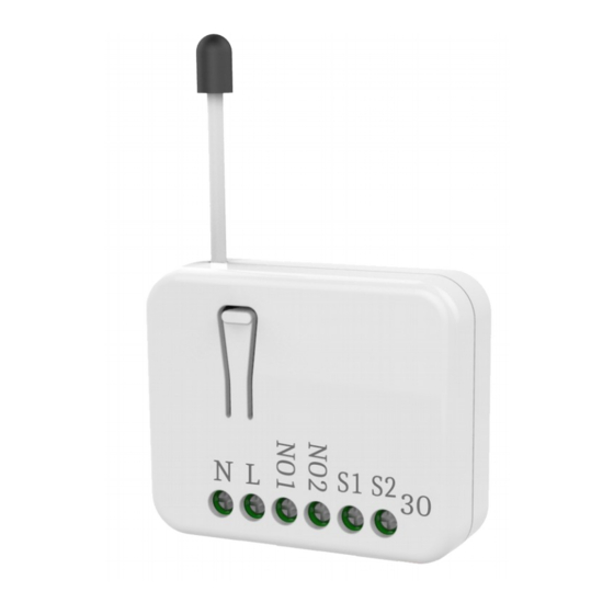
In Wall switch PAN30
Introduction
This in-wall dual relay switch module is a transceiver which is a Z-Wave Plus
enabled device and is fully compatible with any Z-Wave
size design let the module can easily hide itself into the wall box and that will be
good for the house decoration.
There are many kind of application by using the module to switch AC power On
and Off, one main application is the light control. The new smart relay
calibration technology can reduce the inrush current caused by the load and let
the module work perfectly with many kind of light like incandescent, fluorescent
TM
TM
enabled network. Mini
1
and LED light.
This in-wall switch module is able to detect Instant power wattage and overload
current (7.5A with resistive load) of connected light or appliances. When detect-
ing overload state, the Module will be disabled and its On/Off button will be lock-
out of which LED will flash quickly. However, disconnect and re-connect the
Module will reset its overload condition to normal status.
This product can be operated in any Z-Wave network with other Z-Wave
certified devices from other manufacturers. All mains operated nodes within the
network will act as repeaters regardless of vendor to increase reliability of the
network.
Safety Precautions and Installation
Avoid installing the unit in storming or raining weather.
Be sure to isolate or switch off power source before installing or
maintenance.
Do ensure that the power supply circuit protected by a 16A circuit breaker
or suitable equivalent fuse.
IMPORTANT
Installation must be performed by skilled technicians who are informed
about the standards and technical requirements of the appliance and its
proper installation.
Check your local codes as they apply to your situation. If the house wiring
is of aluminum, consult with an electrician about proper wiring methods.
Before proceeding with the installation, TURN OFF THE POWER TO THE
Advertisement
Table of Contents

Related Manuals for Zwave PAN30


Summary of Contents for Zwave PAN30
- Page 1 LED light. In Wall switch PAN30 This in-wall switch module is able to detect Instant power wattage and overload current (7.5A with resistive load) of connected light or appliances. When detect- ing overload state, the Module will be disabled and its On/Off button will be lock- out of which LED will flash quickly.
-
Page 2: Specification
Frequency Range 868.40MHz; 869.85MHz (EU) Installation Steps 908.40MHz; 916.00MHz (USA/Canada) 1. Connect PAN30 to AC N and L. 920.90 MHz, 921.70 MHz, 923.10 MHz (Taiwan) 2. Connect Load1 and Load2 to NO1 and NO2. RF Power +10dBm (Peak), -10dBm (Average) 3. -
Page 3: Danger Of Electrocution
of heat, e.g. fires, radiators, boiler etc. Fig 1. Assembling 4. After putting it into use, the body of Module will become a little bit hot of which phenomenon is normal. For Instruction to http:// www.philio-tech.com Adding to Z-Wave Network In the front casing, there is an on/off button with LED indicator below which is used to toggle switch on and off or carry out inclusion, exclusion, reset or association. -
Page 4: Led Indication
Sometimes people are not easy to execute exclusion or inclusion especially 2. Pressing INCLUDE_BUTTON three times when PAN30 already installed in a wall box. To solve this issue, PAN30 support within 2 seconds will enter exclusion a special feature that can use S1 or S2 to execute “exclusion, inclusion, Reset mode. -
Page 5: Installation
State LED Indication Type Normal Whatever we switch On and off of the PAN30 by S1 S2 or On/ Off button or RF command, the LED will lights up 1 second and then off. No node Under normal operation, when the Switch has not been allocated a node ID, the LED flashes on and off alternately at 2-second intervals. - Page 6 1-2 BASIC_SET / SWITCH_BINARY_SET For group 2, the Switch will report ON/OFF status of Relay1. Since PAN30 has two relay, all the loads attached to relay1 and relay2 will For group 3, the Switch will report ON/OFF status of Relay2.
- Page 7 Example: 2-1-3 Notification report command Meter Value 1 = 0x00 (W) When PAN30 detect the overload, it will send Notification Report to Group1. Meter Value 2 = 0x00 (W) The content of Notification Report Meter Value 3 = 0x03 (W)
- Page 8 Meter Value 4 = 0xEA (W) Value 3*256) + (Meter Value 4) = 800.35 (KW/h) Meter(W) = Meter Value 3 *256 + Meter Value 4 = 100.2W 2-2-3 Clearing accumulated power consumption 2-2-2 Accumulated Power Consumption (KW/h) Whenever re-start counting the accumulated power consumption is needed, When receiving Meter Get Command, it will report Meter Report you can use Meter Reset Command to clear it.
- Page 9 You may get the ON/OFF state from endpoint 1 and 2, when endpoint set to 1, When receiving Meter Get Command, it will report Meter Report Command to PAN30 will reply state of Relay1. If endpoint set to 2, PAN30 will reply state of the node asked.
- Page 10 Encapsulation Command, you can switch Relay1 ON/OFF by setting endpoint 0x02) range from 1~2) to 1, or switch Relay2 ON/OFF by setting endpoint to 2. The example of the command show that switch off relay1 of PAN30 Command Class = 0x25 (Command Class Switch Binary = 0x25) COMMAND_CLASS_MULTI_CHANNE...
- Page 11 COMMAND_CLASS_MULTI_CHANNEL MULTI_CHANNEL_CMD_ENCAP Source End Point = 0x03 2-3-3 METER_SUPPORTED_GET: (Bit Address +Destination End Point = This command is to ask the endpoint of PAN30 what kind of meter data can be 0x01) reported. Command Class = 0x32 (Command_Class_Meter_V3 = 0x32)
- Page 12 (Meter report = Endpoint3) 2-3-5 METER_GET: (Bit Address +Destination End Point = (Bit Address =0;Destination End Using meter get command to get the KWH, W, V, I, PF from endpoint of PAN30 0x01) Point = command inquirer’s 2-3-5-1 Get KWH from endpoint...
- Page 13 Parameter 1 = 0x10 (Scale = W = 0x02) 0,Size = 4) Parameter 3 = 0x00 Accumulated Power Consumption = PAN30 Instant Power Consumption (W) Report example: 0x000005FD = 15.33 KWh Parameter 4 = 0x00 COMMAND_CLASS_MULTI_CHANNEL Parameter 5 = 0x05...
- Page 14 (Scale = V = 0x04) MULTI_CHANNEL_CMD_ENCAP Source End Point = 0x01 (this is the endpoint of command PAN30 AC load Voltage report example: inquirer, here we assume endpoint is COMMAND_CLASS_MULTI_CHANNEL 1,if the inquirer doesn’t support multi Channel this value will be 0)
- Page 15 (Meter Get = 0x01) COMMAND_CLASS_MULTI_CHANNE Parameter 1 = 0x28 (Scale = A = 0x05) MULTI_CHANNEL_CMD_ENCAP PAN30 AC load current (I) example: Source End Point = 0x01 (this is the endpoint of command inquirer, here we assume endpoint is 1,if the COMMAND_CLASS_MULTI_CHANNEL inquirer doesn’t support multi Channel this...
- Page 16 Description (Byte) 3-1 Watt Meter Report Period: Parameter If the setting is configured for 1hour (set value =720), the PAN30 will report its Watt Meter 720*5s=3600s= instant power consumption every 1 hour to the node of correspond Group. Report Period...
- Page 17 Relay2 over this value, PAN30 will send KWh Meter Report command to the 3-7-2 5% : When the differential value of Watt is over 5%, PAN30 will send a node of correspond Group, minimum value is 1KWh and default value is 10000 meter report to the associated group.
- Page 18 Firmware update over the air (OTA) Indicator Highest granted Security Class PAN30 is based on 700 series SoC and supports Firmware Update Command Manufacturer Specific Highest granted Security Class Class, it can receives the updated firmware image sent by controller via the Z-...
- Page 19 This equipment has been tested and found to comply with the limit’s fora Class B digital 「取得審驗證明之低功率射頻器材,非經核准,公司、商號或使用者均不得擅自變 device, pursuant to Part 15 of the FCC Rules. These limits are designed to provide rea- 更頻率、加大功率或變更原設計之特性及功能。 sonable protection against harmful interference in a residential installation. This equip- 低功率射頻器材之使用不得影響飛航安全及干擾合法通信;經發現有干擾現象時,...
Need help?
Do you have a question about the PAN30 and is the answer not in the manual?
Questions and answers