Advertisement
Quick Links
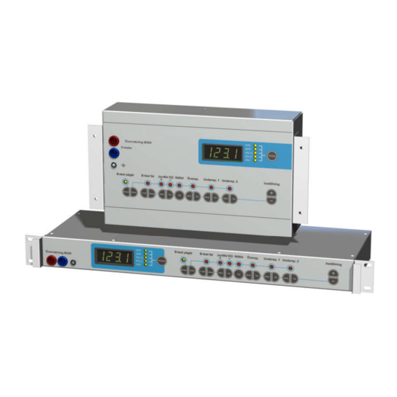
Monitoring M-series
Manual
19" and Wall
English
Manual for M-series monitoring unit
with firmware ver. 102 and later.
For support and information:
Extron AS
Tel: (+47) 63 83 33 90
Mobile: (+47) 90 03 23 94
post@extron.no
www.extron.no
Nedre Rælingsvei 261
N-2008 FJERDINGBY
Manual M-series
MA1479-1.doc
Advertisement

Summary of Contents for Extron electronics M Series
- Page 1 Manual M-series MA1479-1.doc Monitoring M-series Manual 19” and Wall English Manual for M-series monitoring unit with firmware ver. 102 and later. For support and information: Extron AS Tel: (+47) 63 83 33 90 Mobile: (+47) 90 03 23 94 post@extron.no www.extron.no Nedre Rælingsvei 261 N-2008 FJERDINGBY...
- Page 2 Manual M-series MA1479-1.doc Foreword M-series are monitoring units for DC-systems with voltage range 9 – 300 VDC. For monitoring of DC-voltage, DC-current, earth fault and AC-voltage and also triggering of battery test. Settings are easily made with buttons on the front panel and momentary value/setting is shown in the display.
- Page 3 Manual M-series MA1479-1.doc Installation 19” Unpack Open box and find follow parts: 1 pcs. monitoring unit M-series 1 pcs. manual 1 pcs. set of male connectors for connection on backside 1 pcs. connected cable for earth fault sensing 1 pcs. set of attached nuts and washers on earth bolt Install the unit in the 19”...
- Page 4 Manual M-series MA1479-1.doc Connections left Illustration for M300 19”. M100/200 has fewer connections which is shown by the label on the unit. The wall model has the corresponding connectors internally as the 19”. For connection of the safety earth on Wall model use the same screw as for earth fault sensing. Mains alarm relay in/out (only M300), Used with external main fault relay.
- Page 5 Manual M-series MA1479-1.doc Connections left Illustration for M300 19”. M100/200 has fewer connections which is shown by the label on the unit. The wall model has the corresponding connectors internally as the 19”. Relay outputs B open when alarm S closed when alarm G common Mains fault (only M300) Low DC voltage 2 (only M200/300)
-
Page 6: Front Panel
Manual M-series MA1479-1.doc Front panel Below is explanation of front panel. The different models in the M-series are different in form and function and all features may not be present on delivered unit. Measurement connectors, display, display indicators and display button Buttons for choosing what to display Indicators for what is displayed The display shows momentary values or adjustment... - Page 7 Manual M-series MA1479-1.doc Buttons B-test: Start/stop battery test. If no battery test is in progress the battery test is started with the length that is set by using the ”length-button”. If pressed while battery test is in progress the battery test is stopped. Both manual and automatically started tests can be stopped.
-
Page 8: Service Menu
Manual M-series MA1479-1.doc Service menu The service menu is used for calibration and other settings. It is used when testing the unit before leaving the factory and can be used when the installer wants to adapt the units in a more advanced way than is being offered by only using the normal settings. - Page 9 Manual M-series MA1479-1.doc List of service menu settings Choose the menu by pressing +/-. Start adjusting the setting by pressing Display button and +/-. LED/indicator test. All indicators on the front panel and all segments in the 4-digit display is lit. Relay-test.
- Page 10 Manual M-series MA1479-1.doc Calibration of DC-voltage. Connect calibrated V-meter in the V-meter output. Press Display button and use +/- to set the same value in display as the V-meter is showing. Release Display button. Calibration is finished. Calibration of earth fault display is recommended after calibration of voltage. The unit is calibrated before delivery from factory.
- Page 11 Manual M-series MA1479-1.doc Set battery test voltage level (only M300). Set this to a level just above the level the rectifier is set to when doing battery test. The monitoring unit triggers the rectifier to go to battery test level with the battery test relay. At the same time the monitoring unit is measuring the DC-voltage from the rectifier/battery.
- Page 12 Manual M-series MA1479-1.doc Setting of low input voltage protection level. Press display and use +/- to set level. When DC voltage is below set level the unit shuts off. When the DC-voltage goes back above set voltage (plus hysteresis) the unit turns on. The level cannot be set more than 95% of the momentary DC-voltage.
- Page 13 Manual M-series MA1479-1.doc Setting of hysteresis for low DC voltage 1. If the voltage is lower than set level the alarm is triggered. The voltage must then go above the set level plus this hysteresis level in order for the alarm to become inactive. Example: voltage <...
- Page 14 Manual M-series MA1479-1.doc Setting of hysteresis for low input voltage protection. If the DC-voltage is lower than set level the unit shuts off. The DC-voltage must then go above the set level plus this hysteresis level in order for the unit to turn on. Example: DC-voltage <...
-
Page 15: Technical Data
Manual M-series MA1479-1.doc Technical data Input voltage 9-36 VDC, 18-75 VDC eller 70-300 VDC Alarm levels High DC voltage/low DC voltage: Measuring the DC-voltage. Alarm level possible: 1-300V. Earth fault: Alarm level possible: 50-1000Kohm. Delay of all alarms except battery test: 1-1800 sec or blocking. Separate settings for level/delay: High DC voltage, low DC voltage 1, low DC voltage 2, earth fault +/-, battery test level (only M300), mains fault with AC-input (only M300).
Need help?
Do you have a question about the M Series and is the answer not in the manual?
Questions and answers