
Summary of Contents for ALTAI MIS200P
- Page 1 Quick Setup Guide ALTAI MIS200P Industrial 14-Gigabit-Port Managed PoE Switch ______________________________________________ Quick Setup Guide Version 1.1 Altai Technologies Ltd. All rights reserved...
-
Page 2: Package Content
Quick Setup Guide 1. Introduction Thank you for purchasing the Altai MIS200P product. This guide provides instructions to install the product and set it up with minimal effort. 2. Package Content MIS200P Main Unit x 1 pc • DC Terminal Block Connector x 1 pc •... -
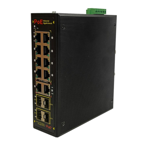
Page 3: Product Description
Quick Setup Guide 3. Product Description Altai MIS200P is an industrial-grade managed switch featuring eight 1GbE PoE ports, two 1GbE copper ports and four 100/1000BASE-X SFP slots. The switch, with a rugged IP40 metal case and an ultra-wide temperature range from -40°C to 80°C, is designed to operate in harsh industrial environments... -
Page 4: Feature Highlights
• Support up to 255 VLAN groups and 4094 VLAN IDs • Support IGMP snooping v1/v2 • Support 802.1X RADIUS user access authentication • Support SSH, SSL, and SNMP v1/v2/v3 management • Support status monitoring by AltaiGate or AltaiCare On Premises Altai Technologies Ltd. All rights reserved... - Page 5 Quick Setup Guide 5. Applications Deployment Scenario 1 The MIS200P is specifically designed to work with Altai APs. A typical use case is as an access switch for an outdoor site, where multiple APs and other devices are co-located. AltaiCare/AltaiGate...
- Page 6 RTG or AGV for connecting a Wi-Fi CPE such as A2x and VX200 to VMT (Vehicle-Mounted Terminal) and Camera. Access Point MIS200P 18-32V DC IP Camera Vehicle-Mounted Terminal Mobility Applications in Container Terminal: Quay Crane Altai Technologies Ltd. All rights reserved...
-
Page 7: Hardware Overview
Quick Setup Guide 6. Hardware Overview Physical Dimensions Front Panel Back Panel Altai Technologies Ltd. All rights reserved... - Page 8 Two wiring standards can be used for a RJ-45 connector: T568A or T568B. The latter one is preferable for new networks. For details of pin assignments of T568A/T568B wiring specifications, see Appendix A and B. Altai Technologies Ltd. All rights reserved...
- Page 9 Quick Setup Guide MIS200P switch also supports auto MDI/MDI-X operation. Therefore, you can use either straight-through or crossover cables to connect the switch with any other network devices. For simplicity, it is recommended to use straight- through cables. For details of wiring for a straight-through or crossover cable using T568B specification, see Appendix C and D.
- Page 10 LX to 1000BASE-LX. Also, check whether the fiber-optic cable type matches with the SFP transceiver requirement, e.g. single-mode or multi-mode, connector types. SFP Transceiver Note: SFP transceiver modules are not included in the package. Altai Technologies Ltd. All rights reserved...
- Page 11 3. Grasp the bail latch and pull the transceiver out of the slot gently. Bail Latch D: Reset Button For factory reset. To do so, press and hold the reset button for 10 seconds, then release it immediately. Altai Technologies Ltd. All rights reserved...
- Page 12 Link disconnected or failure G: Power Status Indicator of PoE Port Indicator Color State Description Green Power delivery to PD properly Blinking Power overload or failure Not connected to PD or PoE feature powered Altai Technologies Ltd. All rights reserved...
- Page 13 For installation details, see section DIN-Rail Mounting Instruction. K: DC Terminal Block Receptor/Connector (6-Contact) Used for two DC redundant power input and fault relay. For details, see section Power Connection and Fault Relay respectively. Altai Technologies Ltd. All rights reserved...
- Page 14 Used with a RJ-45 to RS232 DB9 console cable for local access and management. To make the console connection, the following terminal settings are required. • Baud rate: 115200 • Data bits: 8 • Stop bits: 1 • Parity: None • Flow control: None Altai Technologies Ltd. All rights reserved...
- Page 15 • Disconnect the unit from power source during installation. • Avoid mounting the unit in dusty areas and areas with strong electromagnetic interference. Installation To mount the MIS200P unit on the rail, follow the steps below: Bracket 1. Insert the upper bracket lip into 35mm Rail the DIN rail.
-
Page 16: Power Connection
MIS200P switch supports dual DC power inputs via a terminal block connector. To power up the MIS200P switch, you are required to prepare the following. • 48–57V DC power input if the switch is used to support PoE feature for 802.3af/at PDs;... - Page 17 3. Insert the terminal block into the receptor. Use the flat-blade screwdriver to lock the terminal block to the MIS200P unit in place. 4. Connect the positive and negative DC wires to a power source(s).
- Page 18 SD.PE-0001-MW Industrial power supply, 100 – 240 VAC in, 48 VDC @ 2.5A out, 120W, DIN rail mount SD.PE-0002-MW Industrial power supply, 100 – 240 VAC in, 48 VDC @ 5A out, 240W, DIN rail mount Altai Technologies Ltd. All rights reserved...
-
Page 19: Fault Relay
Quick Setup Guide 9. Fault Relay MIS200P supports fault relay, which consists of contacts 5 and 6 of the terminal block, to indicate the power fault event. Insert two wires (size: 12 – 18 AWG) into the relay contacts. When power fault occurs, the two wires attached to the relay contacts form an open circuit. - Page 20 3. Type in the following IP address and Subnet mask: • IP address: 192.168.1.3 • Subnet mask: 255.255.255.0 4. Click OK to close the Internet Protocol Version 4 (TCP/IP) Properties dialog box and click OK again to close the adapter Properties dialog box. Altai Technologies Ltd. All rights reserved...
- Page 21 3. If successful, you will be brought to the following page. From now on, you can start configuration for the switch. For details of Web UI operation, refer to the Web UI Configuration Manual. Altai Technologies Ltd. All rights reserved...
- Page 22 2. Login to the switch with the correct username/password and port number. By default, • Username: admin • Password: admin • Port Number: 22 For details of CLI operation, refer to the CLI User Manual. Altai Technologies Ltd. All rights reserved...
-
Page 23: Appendix A - T568B Wiring Specification For Ethernet
RD+ with PoE Input- BI_DB+ with PoE Input- Blue Unused BI_DC+ White/Blue Unused BI_DC- Green RD- with PoE Input BI_DB- with PoE Input- White/Brown Unused BI_DD+ Brown Unused BI_DD- 1 2 3 4 5 6 7 8 Altai Technologies Ltd. All rights reserved... -
Page 24: Appendix B - T568A Wiring Specification For Ethernet
RD+ with PoE Input- BI_DB+ with PoE Input- Blue Unused BI_DC+ White/Blue Unused BI_DC- Orange RD- with PoE Input BI_DB- with PoE Input- White/Brown Unused BI_DD+ Brown Unused BI_DD- 1 2 3 4 5 6 7 8 Altai Technologies Ltd. All rights reserved... - Page 25 Appendix C – Pin Assignments and Wiring for a Straight-Through Cable using T568B Standard 1 2 3 4 5 6 7 8 1 2 3 4 5 6 7 8 End A End B Altai Technologies Ltd. All rights reserved...
- Page 26 Appendix D – Pin Assignments and Wiring for a Crossover Cable using T568B Standard 1 2 3 4 5 6 7 8 1 2 3 4 5 6 7 8 End A End B Altai Technologies Ltd. All rights reserved...
- Page 27 This document is provided for information purposes only. Altai Technologies reserves the right to change, modify, transfer, or otherwise revise this publication without notice.
Need help?
Do you have a question about the MIS200P and is the answer not in the manual?
Questions and answers