Table of Contents
Advertisement
Quick Links
Advertisement
Table of Contents

Summary of Contents for Iwatsu SE-6000
- Page 1 Instruction Manual Isolation Probe SE-6000 SE-6011...
- Page 2 © 2016 IWATSU ELECTRIC CO., LTD. All rights reserved....
-
Page 3: Introduction
◇ Reproduction of the contents of this manual, in part or whole, without previous consent is prohibited. ◇ For questions about this instrument, contact Iwatsu office or our sales distributors. History ◇ July 2016: Issue of the 1st edition... -
Page 4: Warnings
Read the following safety information. [Read the next page.] Warnings To prevent electrical shock, never touch the probe cable if a circuit to be measured is connected to the Isolation Unit during measurement. For explanations of floating measurement, refer to “7.1 Precautions when using probes during floating measurement.”... - Page 5 (2) Disconnect the power plug from the receptacle. Failure to do so may cause an electrical shock or fire. After taking the above actions, contact Iwatsu office or our sales distributors for repair. Never repair this instrument by yourself, doing so is...
- Page 6 (Isolation Amplifier: “ ”, Isolation Unit: “standby” where the switch is turned to position), and disconnecting the power plug from the receptacle, contact Iwatsu office or our sales distributors for repair. Use a 3-core power cord for the Isolation Amplifier.
- Page 7 Modification or repair by the customer may cause an electric shock, fire, or malfunction. This instrument cannot be repaired by the customer. Do not repair this instrument by opening the cover. Contact Iwatsu office or our sales distributors for repair. Note that we cannot undertake the repair if the seal for tampering detection has been peeled off, the cover has been opened, or modification has been done.
- Page 8 (Isolation Amplifier: “ ”, Isolation Unit: “standby” where the switch is turned to position), and disconnecting the power plug of the Isolation Amplifier from the receptacle, contact Iwatsu office or our sales distributors for repair. Do not place this instrument where it may be subject to vibration or shock.
-
Page 9: Cautions
Unless specified otherwise at the time of purchase, a power cord rated for 100V system (90V to 132V) is provided. If the supply voltage is 200V system (180V to 250V), use the optional 200V 3-core power cord (rating: 250V) designated by IWATSU. Place this instrument properly so that power cord can be easily unplugged. - Page 10 Large vibrations or shocks applied to this instrument during transportation may cause a power failure or a fire. If no appropriate packing material or cushion material is available, contact Iwatsu office or our sales distributors. When using a carrier, label “precision machine” on each face of the packing box.
- Page 11 This instrument uses a dedicated battery pack. Replacing the battery pack with an incorrect type poses a risk of explosion. When the service life of a battery pack has ended, be sure to purchase the correct new battery pack from IWATSU.
-
Page 12: Checking Packed Materials
When receiving this instrument, confirm the type and number of the instrument, and check the main unit and accessories while referring to the following “Components.” (For unpacking, see next page.) If there is a missing item or an item damaged during transportation, immediately contact Iwatsu office or our sales distributors. Components Isolation Amplifier SE-6000... -
Page 13: Unpacking (Isolation Amplifier Se-6000)
Unpacking (Isolation Amplifier SE-6000) Instruction manual sleeve Isolation Amplifier Accessory sleeve * When box is opened. Unpacking (Isolation Unit SE-6011) Accessory (precautions) Isolation Unit... -
Page 14: Management Of Instrument
Repair and sending instrument to be repaired If a failure occurs, send this instrument to Iwatsu office or our sales distributors. Malfunctions that occur during the warranty period due to our responsibility will be repaired by us free of charge. - Page 15 Instruction Manual...
-
Page 17: Table Of Contents
1.3 System configuration and overview (functions)................1-3 1.4 Options/Accessories ........................1-4 Chapter 2 Exterior features and basic operations ..........2-1 2.1 Exterior features of Isolation Amplifier (SE-6000) and its overview ..........2-2 2.1.1 Exterior features of front panel and its overview ..............2-2 2.1.2 Exterior features of rear panel and its overview .............. - Page 18 3.1.3 Power cord connection/power on (Isolation Amplifier SE-6000)..........3-5 3.2 Connection of instruments ....................... 3-6 3.3 System startup ..........................3-7 Chapter 4 Function setting ...................4-1 4.1 CH menu ............................4-2 4.1.1 RANGE........................... 4-4 4.1.2 BANDWIDTH ......................... 4-9 4.2 SAVE menu ........................... 4-10 4.3 RECALL menu ..........................
-
Page 19: Chapter 1 Overview
Overview 234567 Chapter 1 Overview... -
Page 20: Applications
1.2 Characteristics This instrument is a system consisting of an Isolation Amplifier (SE-6000), Isolation Unit (SE-6011), battery pack, and optical fiber cable (see 1.3). Characteristics of this system will be explained below. -
Page 21: System Configuration And Overview (Functions)
Overview System configuration and overview (functions) This instrument is a system where the Isolation Amplifier (SE-6000) and Isolation Unit (SE-6011) are connected by optical fiber cable. (See Figure 1.1) Probe, etc. Isolation Unit I Optical fiber cable Battery pack Monitor (digital oscilloscope, etc.) -
Page 22: Options/Accessories
Battery pack (one set) CH5050A Battery charger Accessories The accessories shown below can be purchased separately from the accessories shown on page x. • Instruction Manual (CD) • User's Guide (paper format) Please order spare parts from Iwatsu office or our sales distributors. -
Page 23: Chapter 2 Exterior Features And Basic Operations
Exterior features and basic operations 34567 Chapter 2 Exterior features and basic operations In this chapter, exterior features and basic operations of this instrument are explained as follows. • 2.1: Isolation Amplifier • 2.2: Isolation Unit, battery pack, battery charger, insulation cover, etc. •... -
Page 24: Exterior Features Of Isolation Amplifier (Se-6000) And Its Overview
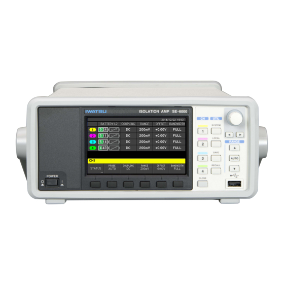
Table 2.1. ④ ③ Figure 2.1 Front panel of SE-6000 Table 2.1 Explanations of each section of front panel of SE-6000 Names Explanations See also Display section The display section consists of the LCD display and six menu keys ... - Page 25 Exterior features and basic operations 2.1.1.1 FUNCTION section Figure 2.2 shows the FUNCTION section of the front panel, and the functions and name of each part are explained in Table 2.2. Figure 2.2 FUNCTION section Table 2.2 Functions and name of each part of FUNCTION section Names Functions (summary)
- Page 26 Exterior features and basic operations 2.1.1.2 Rotary knob & RANGE section Figure 2.3 shows the rotary knob and RANGE section, and the name of each part and its functions are explained in Table 2.3. When rotary operation is enabled, the circle around the knob lights up green.
-
Page 27: Exterior Features Of Rear Panel And Its Overview
Figure 2.4 Rear panel of SE-6000 Table 2.4 Exterior features of rear panel of SE-6000 and its overview Name Explanations and overview of functions See also AC LINE INPUT • This is a power inlet socket. Use the attached power cord for 3.1, 3.2... -
Page 28: Exterior Features Of Isolation Unit (Se-6011), Related Parts, And Overview
Exterior features and basic operations 2.2 Exterior features of Isolation Unit (SE-6011), related parts, and overview Exterior features of the front panel and its overview is explained in 2.1.1. Instructions and precautions for handling the battery pack, battery charger, and insulation covers are explained from 2.2.2 to 2.2.4. - Page 29 Exterior features and basic operations Table 2.5 Exterior features of front panel of SE-6011 and its overview Names Explanations See also POWER switch This is the POWER switch of the Isolation Unit. 3.1.3 • On: When the switch is pushed to the I side. •...
-
Page 30: Battery Pack
Exterior features and basic operations 2.2.2 Battery pack 2.2.2.1 Instructions for handling (1) Mounting/dismounting The battery pack is delivered with 50% of its full capacity charged. It is possible to use the battery pack as delivered; however, we recommend charging it fully before performing measurements. * For charging battery packs, see 2.2.3. - Page 31 Exterior features and basic operations Black tape Battery pack Figure 2.6 (c) Without internal cover (2) Storage If you do not have a plan to use the Isolation Unit in the immediate future, take the battery pack out from the Isolation Unit, and keep it separately under an environment of about 5°C to 20°C.
- Page 32 Exterior features and basic operations 2.2.2.2 Display of available capacity of battery pack You can check the available capacity of the battery pack by the screen of the Isolation Amplifier, by level indicators of the battery pack, and by BATTERY lamps of the Isolation Unit. Among them, level indicators of the battery pack are only for rough guideline, and for more accurate value of available capacity, see the screen of the Isolation Amplifier.
- Page 33 Exterior features and basic operations Variations of the battery icons and their meanings are as shown in Table 2.6. Available time of the battery pack is displayed inside the battery icon of the currently used battery pack in the format of XX: YY which means XX hours YY minutes as shown in Figure 2.7 on the previous page Table 2.6 Battery icons and available capacity Not in Meaning...
- Page 34 Even under room temperature, a battery pack inevitably degrades after several hundred cycles of charging and discharging. Normally this instrument can be operated for approximately 15 hours with one battery pack. Contact Iwatsu office or our sales distributors for consultation when operation duration becomes shorter than the norm.
-
Page 35: Charging Battery Pack
Stop charging and do not use the battery pack. Contact Iwatsu office or our sales distributors for consultation. Additionally, accessories of the battery charger are written in <Options> of Components on page x, and specifications are described in 6.1.3. - Page 36 Exterior features and basic operations (2) Procedures for charging <Preparation (common to charging only, and charging and calibration mode)> 1) Insert the DC connector plug of the AC adaptor to the DC connector socket (female, see Figure 2.9) of the battery charger. 2) Connect the AC adaptor and the attached power cord (3-core).
-
Page 37: Insulation Cover
Exterior features and basic operations 2.2.4 Insulation cover The insulation cover not only insulates the units from each other, but also prevents electric shock to the operator when voltage is applied during measurements. Maximum withstanding voltage of the insulation cover is 1kV. All the electrically conductive parts of the housing of the Isolation Unit are covered by the insulation cover, and only the insulation cover of the front panel is detachable. -
Page 38: Protection Function For Temperature (Overheat Prevention)
Exterior features and basic operations 2.2.5 Protection function for temperature (Overheat prevention) This instrument monitors the internal temperature of the Isolation Unit at all times, and shuts down the power of the Isolation Unit automatically if temperature goes beyond the designated range. (1) Temperature monitor The temperature of each Isolation Unit is monitored with the corresponding CH/STATUS/TEMPERATURE menu as shown in the figure below. -
Page 39: Screen Layout And Basics Of Menus
2.3.1 Screen layout When this instrument is turned on, the startup screen with the IWATSU logo is displayed for several seconds before turning into the normal screen. An example of the normal screen is shown in Figure 2.12. - Page 40 Exterior features and basic operations <Readout display area> The readout display area shown in of Figure 2.12 is explained in Figure 2.13 and Table 2.8. Figure 2.13 Example of normal screen (CH menu) Table 2.8 Name of each part and overview of readout display area Names Explanations...
-
Page 41: Basics Of Menus
Exterior features and basic operations 2.3.2 Basics of menus Basic operations of whole procedures from setting to using this instrument are explained. Operations using the menu displayed at the bottom of the screen are explained together with complex operations involving keys and rotary knob (switch). ... - Page 42 Exterior features and basic operations Operation Procedures 2. Open submenu Press the M3 key in the SYSTEM menu shown below. The BEEP & DISPLAY submenu opens as shown below. Operation Procedures 3. Close submenu Press the [CLOSE] key or the rotary knob shown in Figure 2.14 on the previous page in the BEEP &...
- Page 43 Exterior features and basic operations 2.3.2.2 Select item within the menu How to set SYSTEM/BEEP & DISPLAY/BACKLIGHT: LOW is explained as an example. Operation Procedures 1. Select an item within the menu. Press the M3 key in the SYSTEM menu shown below. The BEEP & DISPLAY submenu opens as shown below in 2).
- Page 44 Exterior features and basic operations 2.3.2.3 Set value to item within the menu How to set CH1/OFFSET: +100mV is explained as an example. 1. Set value to an item within the menu (Change OFFSET value from +0.000V Operation Procedures to +100mV) Press the M5 key in the CH1 menu shown below.
- Page 45 Exterior features and basic operations 2.3.2.4 Set characters to item within the menu Directory and file names are necessary to save setting conditions to external memory such as USB memories. Default settings are as follows. File names are automatically changed every time by adding the subsequent number at the end.
- Page 46 Exterior features and basic operations Press the M2 key in the above 3) to select DIRECTORY. The DIRECTORY menu opens as shown below. Press the right arrow key under the rotary knob to select the character position to input. Press the M4 key to select symbols of [!#$] which are beneath the menu. Continue editing as shown below using the rotary knob, arrow key, and menu key.
- Page 47 Exterior features and basic operations Press the M3 key to open the FILENAME menu shown in the figure after the next. Edit file name using the rotary knob, arrow key, and menu key as shown below, which are the same procedures described in 5) on the previous page. Press the [CLOSE] key when finished editing in 8).
- Page 48 Exterior features and basic operations 2.3.2.5 Implement setting items within menu In the case of the SAVE/RECALL menu explained in the previous section 2.3.2.4, each item is implemented when pressing the menu key of M1 - M6 after all the procedures are finished. To indicate the menu to implement an actual command, a “return mark”...
-
Page 49: Chapter 3 Installation And Preparations
Installation and preparations 4567 Chapter 3 Installation and preparations In this chapter, preparations and construction of measurement systems using this instrument are explained. -
Page 50: Precautions For Installation
Installation and preparations 3.1 Precautions for installation This instrument has to be installed to a place where environmental conditions conform to “3.1.1 Installation conditions” written below. Additionally, make sure to read “Safety Precautions” at the beginning of this document for warnings and cautions. For actual setup, see “3.1.2 Installation states.”... -
Page 51: Installation States
Installation and preparations 3.1.2 Installation states (1) Isolation Amplifier Place horizontally or at a slant using the handle as shown in Figure 3.1 (a) or (b). To rotate handle, widen the handle at its joint to the body, rotate to any one of the positions shown in Figure 3.1 (a), (b), and (c), and push the handle back to lock. - Page 52 Installation and preparations (2) Isolation Unit The installation state A shown in Figure 3.2 (a) is the standard position. It is also possible to set the Isolation Unit with the battery pack downward as shown in Figure 3.2 (b) (installation state B). Hand grip NUMERIC Insulation cover...
-
Page 53: Power Cord Connection/Power On (Isolation Amplifier Se-6000)
Installation and preparations 3.1.3 Power cord connection/power on (Isolation Amplifier SE-6000) Warnings and cautions for the power cord and wiring of power cord are explained in the beginning of this manual on pages iii to viii. Make sure to read these warnings and cautions before connecting this instrument to power supply. -
Page 54: Connection Of Instruments
Installation and preparations 3.2 Connection of instruments Connection of instruments to construct the whole measurement system of this instrument is explained. * In this example, the Isolation Unit is connected to CH1. Instruments and schematic illustration of the whole measurement system Monitor Isolation Unit Probe... -
Page 55: System Startup
Installation and preparations 3.3 System startup After “Connection of instruments” explained in 3.2, start up the system with the following procedures. In this example, the input signal of Isolation Amplifier SE-6000 is monitored by digital oscilloscope DS-5654A. Procedures for system startup (1) Power on Push the POWER switches of 1) to 3) written below to turn them on. - Page 56 Installation and preparations <In the case of DC 1MΩ> 1) Set each parameter in the SYSTEM menu of Isolation Amplifier SE-6000 as follows. a) SYSTEM/RANGE/OUTPUT ±1V (50Ω) ±2V (1MΩ) b) SYSTEM/RANGE/SCALE 1/8DIV Since output is set to ±1V at 50Ω load, ±2V, which is twice the value for 50Ω load, is output with 1MΩ...
- Page 57 Installation and preparations (6) Deskew of digital oscilloscope DS-5654A When signals from multiple channels are input to the Isolation Amplifier and monitored by the digital oscilloscope, delay time may be different for each channel due to difference in length of optical fiber cable or electrical path.
-
Page 58: Chapter 4 Function Setting
Function setting Chapter 4 Function setting In this chapter, function settings of each CH and the whole system of this instrument are explained. -
Page 59: Menu
Function setting 4.1 CH menu Each Isolation Unit corresponds to one CH. Up to 4 channels can be connected to one Isolation Amplifier. Settings of each Isolation Unit are performed by the CH menu of the Isolation Amplifier. In this section, the CH menu screen, setting procedures, and details of settings are explained. The keys CH1 to CH4 of the Isolation Amplifier correspond to the menu of CH1 to CH4, respectively. - Page 60 Function setting CH menu items and details of settings Menu items (1st) Menu items (2nd) Details See also 6.1.1 To display information of Isolation Unit connected to the CH. • To display model name of the Isolation Unit connected to the CH. -...
-
Page 61: Range
Function setting 4.1.1 RANGE Over-range display, auto range function, and the relationship among the RANGE displayed in CH menu, output range of Isolation Amplifier, input range of Isolation Unit, RANGE SCALE etc., are explained below. 4.1.1.1 RANGE displayed in CH menu Input range of Isolation Unit is centered at set value−OFFSET as shown in Figure 4.1 (a) on the next page, and actual ranges are shown in Table 4.1. - Page 62 Function setting *1. 1/1 is set with RANGE SCALE in SYSTEM menu. These values correspond to full-scale of voltage, and are voltage values relative to the offset settings. *2. 1/8DIV is set with RANGE SCALE in SYSTEM menu. These values are voltage of 1div displayed by oscilloscope. *3.
- Page 63 Function setting Screens of most oscilloscopes are divided into 8 divisions vertically or voltage-wise as shown in Figure 4.2, and voltage value par division is set to the voltage rage (unit: V/div). If you set RANGE SCALE of SYSTEM menu to 1/8DIV, 1/8 of the voltage input range can be displayed to the RANGE of each CH, which corresponds to the above-mentioned voltage range of the oscilloscope.
- Page 64 Function setting 4.1.1.2 Over-range display Range value of the CH is displayed in the read out display area inside the screen. If the range value is displayed in red as shown in Figure 4.3 (a), input signal is out of the input range, which is called over-range. In the case of over-range, open the RANGE menu and increase range setting or press the range key (key with upward arrow as shown in Figure 4.3 (c)).
- Page 65 Function setting 4.1.1.3 Auto range function If you press the [AUTO] key, range and offset are set to proper values in accordance with the input signal. If you use the auto range function when a square wave signal of 2.96Vp-p is input as shown in the left figure of Figure 4.4 (a), offset value will be set to −1.48V as shown in the right figure, and screen changes from Figure 4.4 (b) to (c).
-
Page 66: Bandwidth
Function setting 4.1.2 BANDWIDTH There are four selections in the CH/BANDWIDTH menu, and each bandwidth is as shown below. • FULL : Frequency bandwidth is set to 30MHz, which is the maximum bandwidth of the Isolation Unit. • 10 MHz : Excludes components of 10 MHz or more. -
Page 67: Save Menu
Function setting 4.2 SAVE menu Settings shown below can be saved by the SAVE menu. (1) Settings 1) Settings of CH1 to CH4 (PROBE, COUPLING, RANGE, OFFSET, BANDWIDTH) 2) OUTPUT RANGE 3) RANGE SCALE * Items of 1) are to be set in the CH menu, and of 2) and 3) are to be set in the SYSTEM menu. Those settings, 1) through 3), are saved as a set. - Page 68 Function setting Setting procedures and details are explained below. Operation Procedures 1) Press the [SAVE] key to open the SAVE menu. 2) Use the menu at the bottom of the screen for setting. To select menu, use menu keys, M1 to M6, beneath the display or rotary knob.
- Page 69 Function setting Items of SAVE setting menu and details (destination: USB memory) Menu item (1st) Menu item (2nd) Details of setting See also 6.1.2 • To select and set the destination to save the settings from below. • INTERNAL •...
-
Page 70: Recall Menu
Function setting 4.3 RECALL menu You can retrieve settings from sources explained below by the RECALL menu. Content of the retrieved settings are the same as explained in (1) of 4.2 SAVE menu. (1) SOURCE 1) INTERNAL MEMORY You can view the settings currently saved to the internal memory by selecting the corresponding number of internal memory, #1 to #10, in the RECALL/NUMBER menu, as shown in Figure 4.6. - Page 71 Function setting Setting procedures and details of the RECALL menu are explained below. Operation Procedures 1) Press the [RECALL] key to open the RECALL menu. 2) Use the menu at the bottom of the screen for setting. Select menu using menu keys, M1 to M6, beneath the display or rotary knob.
- Page 72 Function setting ◆ Items of RECALL setting menu and details (source: USB memory) Menu item (1st) Menu item (2nd) Details of setting See also • To select and set the source to retrieve the settings from 6.1.2 below. • INTERNAL SOURCE •...
-
Page 73: System Menu
• To initialize all the settings. ABOUT • Display of such information as model name, firmware version number, and internal temperature (SE-6000). Setting procedures and details of the SYSTEM menu are explained below. Operation Procedures 1) Press the [SYSTEM] key to open the SYSTEM menu at the bottom of the display. - Page 74 - * Numerical value setting: Use rotary knob and arrow keys to set numerical values. MISC • SE-6000: To update firmware of Isolation Amplifier. • FIRMWARE UPDATE 4.4.1 • CHn: To update firmware of Isolation Unit connected by optical fiber cable.
-
Page 75: Misc/Firmware Update Menu
Isolation Amplifier. Never turn the power off during the update of firmware of internal hardware. 3) Contact our salesperson or visit our website for firmware update. (http://www.iti.iwatsu.co.jp) 4) Save necessary settings to USB memory using the SAVE function in the SAVE menu (see 4.2) before the firmware update. - Page 76 6) Press the M1 key in the FIRMWARE UPDATE menu, in which current version of firmware is displayed, to select the SE-6000 menu and open the confirmation menu shown in 7) below. 7) Press the M1 key to select YES in the confirmation menu displaying “Are you sure you want to update firmware?”...
- Page 77 (See 4.4.1.1) When you update the Isolation Unit, however, instead of selecting SE-6000 by pressing the M1 key as explained in the step 6 of the previous section, press one of the M2 to M5 keys to select the CH menu of the Isolation Unit you want to update, as shown in the figure below, after confirming the current firmware version of the Isolation Amplifier in the firmware update menu.
-
Page 78: About Menu
Function setting 4.4.2 ABOUT menu To display version information of the Isolation Amplifier. When you select SYSTEM/ABOUT, the menu screen such as shown in Figure 4.7 opens. * Version information, etc., below are displayed. • MODEL : Model name • FIRMWARE VERSION : Firmware version number Figure 4.7 Example of ABOUT THIS INSTRUMENT screen 4-21... -
Page 79: Chapter 5 Daily Check And Calibration
Daily check and calibration 1234 Chapter 5 Daily check and calibration In this chapter, procedures of checking, maintenance, and calibration of this instrument are explained. -
Page 80: Daily Maintenance
5.3.1 Regular calibration For regular calibration of the whole system, contact Iwatsu office or our sales distributors. We recommend that regular calibration be peformed once a year. -
Page 81: Self Calibration Menu
Daily check and calibration 5.3.2 SELF CALIBRATION menu The SELF CALIBRATION menu is provided to maintain the precision of the measurement by performing calibration in accordance with changes of environment such as temperature. For reliable measurements, we recommend regular checking and calibration of this instrument. In this section, calibration using the SELF CALIBRATION menu, which can be performed by the customer, is explained. - Page 82 Daily check and calibration 5.3.2.3 Calibration See (1) and (2) below for the preparation. (1) Connection Isolation Unit Optical fiber cable Battery pack Isolation Amplifier Figure 5.1 Connection for calibration (2) Warm-up Warm up for 30 minutes or more before the calibration (adjustment).
- Page 83 Daily check and calibration (3) Perform calibration with the SELF CALIBRATION menu Operation Procedures 1) Open the CH menu shown below by pressing the CH key to calibrate as shown in the right figure below. (Example: to calibrate CH1) 2) Press the M1 key in the above step to open the STATUS menu shown below.
-
Page 84: Repair And Sending Product For Repair
Daily check and calibration 5.4 Repair and sending product for repair Contact Iwatsu office or our sales distributors in case of malfunctions. Unexpected malfunctions etc., that occur during warranty period due to our responsibility will be repaired free of charge. -
Page 85: Chapter 6 Specifications
Specifications 12345 Chapter 6 Specifications... -
Page 86: Specifications
DC gain accuracy # Condition 1MΩ 50Ω After self-calibration at ±0.3%+[{50Ω terminator error (%)} ±0.3% operation temperature −{SE-6000 output impedance error (%)}]/2 Note ±40mV/50mV range: ±1.5 % ±1%+[{50Ω terminator error (%)} −15°C to +50°C Other range: ±1% −{SE-6000 output impedance error (%)}]/2 Note Note) Formulae for 50Ω... - Page 87 Specifications Attenuation characteristics: −6dB/oct Probesense Auto detection 1:1, 10:1, 100:1, 1000:1 Manual setting 1:1, 20:1, 50:1, 100:1, 200:1, 500:1, 1000:1, 2000:1 CMRR 100dB (at 80Hz) Noise (RMS) 0.05%FS 14 bit 100MS/s Self-calibration Amplitude and offset Calibration output Waveform Square wave Frequency 1kHz±0.5% Output signal amplitude...
- Page 88 Specifications (Excluding protruding parts such as feet, handgrip, and knob) Weight Approx. 2.4kg (Excluding battery pack) Accessory Battery pack (×1)
-
Page 89: Isolation Amplifier (Se-6000)
Specifications 6.1.2 Isolation Amplifier (SE-6000) 14 bit, 100MS/s Output channel BNC type × 4 Output filter 5th-order Bessel filter Output voltage When output range of ±1V (50Ω) or ±2V (1MΩ) is selected 1MΩ termination ±2V 50Ω termination ±1V When output range of ±0.8V (50Ω) or ±1.6V (1MΩ) is selected 1MΩ... -
Page 90: Options
Specifications Output range selection ±1.00V (50Ω)/±800mV (50Ω) Scale display selection 1/1, 1/8DIV Panel lock On/Off Clock function Power supply Input 100 to 240VAC rms ±10% (47 to 63Hz) Power consumption Max. 30VA Overvoltage category Ⅱ Dimensions 226(W) × 100(H) × 366(D) mm (Excluding protruding parts such as feet, handle, and knob) Weight Approx. - Page 91 Specifications 6.2 Certification standards EMC Directive EN61326-1:2013 (Group1,Class A and industrial immunity test requirements) Low Voltage Directive EN61010-1:2010(3rd Edition)
-
Page 92: Appearance
Specifications 6.3 Appearance 6.3.1 Isolation Unit (SE-6011) Unit: mm... -
Page 93: Isolation Amplifier (Se-6000)
Specifications 6.3.2 Isolation Amplifier (SE-6000) Unit: mm... -
Page 94: Chapter 7 Measurements
Measurements 123456 Chapter 7 Measurements... -
Page 95: Precautions When Using Probes During Floating Measurement
Rating voltages of the recommended probe of this instrument are as follows. PHV Series High-voltage probe (PMK) Coaxial cable: 1000V GND lead: 900V Voltage probe SS-101R (Iwatsu Test Instruments) Coaxial cable: 600V GND lead: 300V Measurement voltage (withstanding input voltage) specified to voltage probe is the voltage between probe tip (measurement potential) and GND lead with alligator clip (reference potential). - Page 96 Measurements (1) Case 1 When two IGBTs are measured as shown in Figure 7.1 “Example of floating measurement,” voltage between the reference voltages of probe 1 and probe 2 can reach Ed (V). Therefore, if coaxial cables of these two probes touch, voltage difference between these two ground sheaths can be Ed (V), and numerically, it must be twice or less the rating voltage of the outer sheaths of coaxial cables.
-
Page 97: Message Display
Contact Iwatsu office or our sales distributors for consultation if error persists even after the dispositions written in Table 7.1 (a), (b) are carried out. - Page 98 Measurements Table 7.1 (b) Error messages and details in menu display area Error messages Details (conditions, factors, etc.) Dispositions • SE6000.bin is not found Failed to read USB memory. • Re-insert the USB memory. • Check if the file is normal. on USB memory.
- Page 99 Measurements Status messages described in Table 7.2 (a) to (c) are displayed corresponding to key operations, etc. Table 7.2 (a) Status messages and details in message display area Status messages Details (conditions, factors, etc.) USB memory is connected. USB memory is properly inserted. USB memory is disconnected.
- Page 100 Remote Control Manual...
- Page 101 Contents Chapter 1 Remote control ................... 1-1 1.1 Communication settings ........................1-1 Chapter 2 Remote command ..................2-1 2.1 Commands/Queries ..........................2-1 2.2 *IDN query ............................2-2 2.3 *SAV command............................ 2-2 2.4 *RCL command ........................... 2-2 2.5 RMODE command/query ........................2-3 2.6 RANG command/query ........................
-
Page 102: Chapter 1 Remote Control
Remote control Chapter 1 Remote control Communication settings for remote control of isolation probe SE-6000/SE-6011 (referred to as this instrument hereinafter) are explained. Communication settings This instrument can be controlled from a PC connected or a PC on the same network as shown in Figure 1.1. - Page 103 Remote control [Memo]...
-
Page 104: Chapter 2 Remote Command
Remote command Chapter 2 Remote command Commands and queries to control this instrument by remote control are explained. Commands/Queries Table 2.1 List of commands and queries Commands/Queries Functions See also *IDN? To acquire information of isolation amplifier. *SAV To save settings to internal memory. *RCL To recall settings from internal memory. -
Page 105: Idn Query
Query syntax *IDN? Response format IWATSU,SE-6000,<serial>,<version> <serial> : = serial number of isolation amplifier SE-6000 <version> : = version number of firmware of isolation amplifier SE-6000 *SAV command To save settings of isolation amplifier to internal memory. Command syntax *SAV <num>... -
Page 106: Rmode Command/Query
Remote command RMODE command/query To set or acquire mode of output range of isolation amplifier. Command syntax RMODE <range_mode> Parameter <range_mode> <range_mode> : = {1, 800M} 1: To set output range to ±1.00 V (50 Ω) 800M: To set output range to ±800 mV (50 Ω) Query syntax RMODE? Response format... -
Page 107: Arang Query
Remote command ARANG query To perform auto-range of input range of isolation unit, and return the result. Query syntax <channel>:ARANG? Parameter <channel> : = {C1, C2, C3, C4} Response format <result> <result> : = {+0, +1} +0: Success +1: Failure −1: No link PROBE command/query To set or acquire probe attenuation ratio of input range of isolation unit. -
Page 108: Ofst Command/Query
Remote command OFST command/query To set or acquire input offset of the isolation unit by voltage value including probe attenuation ratio. Command syntax <channel>:OFST <offset> Parameter <channel> : = {C1, C2, C3, C4} <offset> is a voltage value in the format of <NR3 Numeric Response Data>. Query syntax <channel>:OFST? Response format... -
Page 109: Cpl Command/Query
Remote command 2.11 CPL command/query To set or acquire coupling of the probe connected to the specified input channel of the isolation unit. Command syntax <channel> : CPL <coupling> Parameter <channel> : = {C1, C2, C3, C4} <coupling> : = {DC, AC, GND} Query syntax <channel>... - Page 110 7-41 Kugayama 1-chome Suginami-ku Tokyo, 168-8501 Japan Address +81 3 5370 5483 Phone +81 3 5370 5492 Facsimile http://www.iti.iwatsu.co.jp Homepage...
Need help?
Do you have a question about the SE-6000 and is the answer not in the manual?
Questions and answers