
Subscribe to Our Youtube Channel
Related Manuals for Apollo AIM-4SL


Summary of Contents for Apollo AIM-4SL
- Page 1 AIM-4SL Hardware Manual Revision Date: 19 OCT 2011 This manual contains confidential information and may only be reproduced or distributed with the written consent of Apollo Security Sales, Inc. © 2011 Apollo Security Inc.
- Page 2 Apollo Security, Inc. While every precaution has been taken in the preparation of this document, Apollo Security assumes no responsibility for errors or omissions, or for damages resulting from the use of information contained in this document or from the use of programs and source code that may accompany it.
- Page 3 IMPORTANT INFORMATION W A R N I N G HIGH VOLTAGE, AC MAIN POWER SHOULD ONLY BE CONNECTED BY QUALIFIED, LICENSED ELECTRICIANS. ALL APPLICABLE LAWS AND CODES MUST BE FOLLOWED. IF THIS PRECAUTION IS NOT OBSERVED, PERSONAL INJURY OR DEATH COULD OCCUR Power should not be applied to the system until after the installation has been completed.
-
Page 4: Table Of Contents
Door Contact Input (Door Position Switch) ................................. Exit Pushbutton Input (Request To Exit, REX) ................................. Auxiliary Alarm Inputs ................................. 7 Output Relay Wiring ........................... 23 Strike Wiring, General ................................. Strike Suppression Installation ................................. Strike Wiring, Internal Relay ................................. © 2011 Apollo Security Inc. - Page 5 ........................... 32 2 Reader / Keypad ........................... 32 3 Input Zones ........................... 32 4 Output relays ........................... 32 Part V Specifications Part VI Supplemental Figures Part VII Table of Figures Part VIII Revision History Index © 2011 Apollo Security Inc.
-
Page 6: Part I Introduction
Part Introduction... -
Page 7: Overview
Any card reader with standard Wiegand or mag stripe output can be connected to the AIM-4SL. Provided for each of the four readers are exit push button, door contact and other general purpose inputs as well as are on-board strike relay and an additional general purpose relay outputs. - Page 8 Unlocked—Door strike is continuously energized and the door contact input is not monitored. Access is not controlled. o Facility Code—The entire card contents are read by the AIM-4SL, but only the Facility Code is checked, and if it matches a Facility Code downloaded from the AAN/AAM controller, access is granted.
- Page 9 Part Hardware Layout...
-
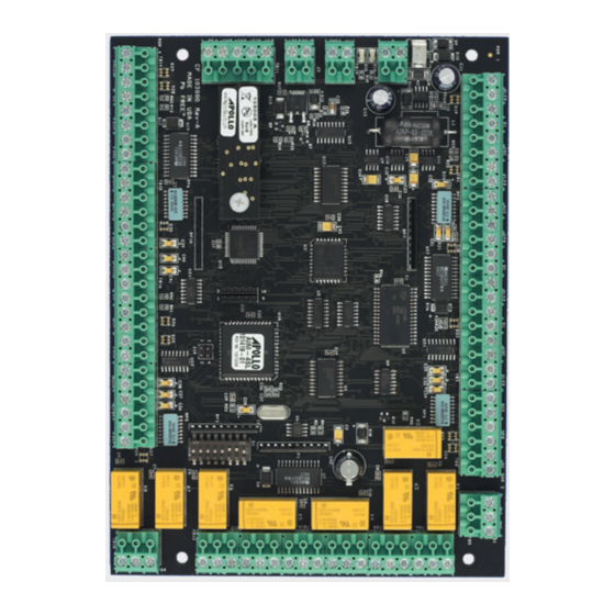
Page 10: Part Ii Hardware Layout
Terminal Connectors The AIM-4SL has 9 terminal blocks for connecting power, reader and alarm inputs, and relay output connections. The connection terminals are factory equipped with removable screw-down quick connectors which are easily removed from the board by firmly grasping the connector and pulling away from the board. - Page 11 AUXR Reader 2 Auxiliary Input (Normally Closed) Auxiliary Input Exit Push Button Return EPBR Reader 2 Exit Push Button (Normally Open) Exit Push Button Door Contact Return Reader 2 Door Contact (Normally Closed) Door Contact © 2011 Apollo Security Inc.
- Page 12 EPBR Reader 4 Exit Push Button (Normally Open) Exit Push Button Door Contact Return Reader 4 Door Contact (Normally Closed) Door Contact Relay Output Connections Common Normally Open Door 1 Strike Relay Connection Normally Closed © 2011 Apollo Security Inc.
- Page 13 20 mA loop Signal Out STRK ADA-10/11 External Relay Loop 20 mA loop Signal Return RET Receive Data (+) Receive Data (-) Transmit Data (+) Serial Communication Connection Transmit Data (-) Signal Ground Table 2.1: AIM-4SL Terminal Connections. © 2011 Apollo Security Inc.
-
Page 14: Dip Switches
AIM-4SL Hardware Manual DIP Switches The AIM-4SL has one block of DIP switches, with 8 switches. These switches are used to set various configuration options for the interface. It is recommended to power the board down before making any changes in the DIP switch settings as any changes will not take effect unless the power is cycled. -
Page 15: Dip Switch Function
The module should be installed so the long end extends towards the middle of the board and the mounting holes provided on the AIM-4Sl and ASM align so a plastic stand-off can be attached to connect the holes. Alternatively, for network configurations, an ENI-100 Ethernet Interface Module can be installed in the socket. -
Page 16: Normal Operation
LED blinks many times a second or lighted solid, depending on the amount of activity. Firmware The operating program for the AIM-4SL is stored in re-programmable flash memory. In the event that the firmware must be re-installed or updated, no chips need to be replaced on the panel. The new program can be loaded from the host via special software. -
Page 17: Additional Installation Information
Hardware Layout Additional Installation Information 2.7.1 Mounting Holes Four holes are provided for mounting the AIM-4SL. Standoffs should be used when mounting in order to protect the underside of the circuit board. © 2011 Apollo Security Inc. - Page 18 AIM-4SL Hardware Manual Figure 2.7.1 AIM-4SL Mounting Holes. Location of mounting holes for the AIM-4SL is shown in scale. Note that the drawing will not print the exact size of the actual circuit board. © 2011 Apollo Security Inc.
- Page 19 Part System Wiring...
-
Page 20: Part Iii System Wiring
Power Power Connection: TB7 Power is supplied to the AIM-4SL by the voltage connection in terminal block 7 (see Part 2.1 for exact locations of terminals). The power connection should be 12-28 VDC. Power consumption is 250 mA. The AIM-4SL is protected from over-current and over-voltage by on-board circuitry. -
Page 21: Safety (Earth) Ground
5. Connect the new unit to the RS-485 line only if no ground fault is found. Communication Connection The serial connection from the AIM-4SL to controller devices is used to collect requests and information from the AIM-4SL to the controller and for the controller to transmit responses to these messages. The AIM-4SL does not originate communication on the device communication lines but waits for a poll from the controller and then establishes communication for configuration. -
Page 22: Rs-485 Communications Line
The controller will serve as “Master” on the line and the other field devices (such as the AIM-4SL) as “Slaves”. There can only be one master per line. The transmit lines of the MASTER device are connected to the receive lines of the SLAVE devices and the receive lines of the MASTER device are connected to the transmit lines of the SLAVE devices. - Page 23 CORRECT CORRECT INCORRECT INCORRECT Figure 3.4.1.1 RS-485 Bus Configuration. The RS-485 communication line must be laid out in a daisy-chain wiring pattern. Avoid wiring devices in a ‘star’ configuration to avoid reflections and termination problems. © 2011 Apollo Security Inc.
-
Page 24: Card Reader Wiring
AIM-4SL power input. There must be sufficient power to supply the load of all readers as well as for the AIM-4SL itself (+12 to +24VDC @ 250 mA). If the readers have a greater total power requirement, or if there are other wiring concerns, external power supplies should be used to power the readers. -
Page 25: Reader Input Wiring
Reader Input Wiring The each of the four reader inputs on the AIM-4SL has three input circuits (Door Contact, Exit Push Button and Auxiliary Alarm 1). These inputs can be configured as UL Grade “B” (unsupervised) or UL Grade “A”... -
Page 26: Input Supervision (Overview)
NOTE: ATM-30 end of line resistors (or an equivalent substitute) are designed to work with the AIM-4SL supervision values on STANDARD AIM-4SL interfaces. The AIM-4SL is available by special order with custom resistor values. In the case of improper function of the supervision, verify what type of AIM-4SL is installed in the system. -
Page 27: Door Contact Input (Door Position Switch)
System Wiring Figure 3.6 Input Supervision. The AIM-4SL reader inputs can be configured for Supervised or Unsupervised. End of line resistors must be used in the supervised configuration in order for the circuits to report the correct state. 3.6.2 Door Contact Input (Door Position Switch) This is a normally closed input and should have a jumper installed if not used! Terminal connectors: DC, DCR (See Table 2.1 ) -
Page 28: Auxiliary Alarm Inputs
A typical electric door lock (strike) will require approximately 250 mA. (.250 amps) to control. The relay contacts on all Apollo relays are capable of switching up to 24 volts DC at up to 2 amps. If the particular locking device requires more that 2 amps to control, a separate, external relay capable of switching the required amount of current must be installed. -
Page 29: Strike Suppression Installation
Strike Wiring, Internal Relay The AIM-4SL Reader Interface includes internal relays for door strike control for each of the four reader inputs. This relay is capable of switching up to 24 volts at up to 2 amps. If the lock installed on the door requires more than 2 amps to control, an external relay must be provided. - Page 30 Figure 3.7.3.1 Strike Wiring Diagram- Fail Secure. A wiring example for Fail Secure wiring. Refer to Table 2.1 for exact locations of strike relay connections for the AIM-4SL. The diagram below illustrates connection of a DC powered, Fail-Safe, door strike. This type of strike requires power to hold the door closed.
-
Page 31: Ada External High Security Relays
Strike Wiring, External ADA-10/11, High Security Relay Use of the internal relays provided on the AIM-4SL reader provides a possible security breach as described above. To prevent the possibility of illegally releasing the door by smashing open the reader and bypassing the internal relay, external, high security relays may be installed. -
Page 32: Additional Output Relay Wiring
Additional Output Relay Wiring Each reader input of the AIM-4SL has the capability of controlling 3 output relays in addition to the strike relay. There are a total of five output relays available. The internal strike relay, an external strike relay, and the three extra output relays. -
Page 33: Ada Dip Switches/Jumpers
The above functions will work the same for each reader. Thus, if reader 2 is selected (S4=ON S3=OFF), and the function Strike Relay is selected (S2=OFF, S1=OFF), the ADA will function as the strike relay for Reader 2. © 2011 Apollo Security Inc. - Page 34 The above functions will work the same for each reader. Thus, if reader 2 is selected (1=CUT, 2=NOT, 3=CUT, 4=CUT), and the function Strike Relay is selected (G1=NOT, G2=NOT), the ADA will function as the strike relay for Reader 2. © 2011 Apollo Security Inc.
-
Page 35: General Alarm Inputs
Cabinet Tamper Input: TB19 This input is for connection to a switch located on the cabinet in which the AIM-4SL is installed to detect unauthorized access to the panel. This is a normally-closed contact. In the event of a tamper condition, the exit push buttons will not function on all 4 reader connections. - Page 36 Part Troubleshooting...
-
Page 37: Part Iv Troubleshooting
The reader function can be verified after communications are functioning properly. The host system must be configured for each of the readers on the AIM-4SL to be used, and with the correct card format. The card format is determined by the actual cards that will be used. After configuring the card format at the host, placing a card in front of the reader should generate an access message on the host computer. -
Page 38: Part V Specifications
Part Specifications... - Page 39 Power Requirements: +12 to +24Vdc @ 250mA Dimensions: 7.5 in x 5.5 in (19 x 14 cm) Environment: Operating Temperature: 0 to 50° C Storage Temperature: -40 to 85° C Relative Humidity: 0 to 95%, non-condensing © 2011 Apollo Security Inc.
- Page 40 Part Supplemental Figures...
-
Page 41: Part Vi Supplemental Figures
Supplemental Figures Supplemental Figures © 2011 Apollo Security Inc. - Page 42 AIM-4SL Hardware Manual © 2011 Apollo Security Inc.
- Page 43 Supplemental Figures © 2011 Apollo Security Inc.
- Page 44 AIM-4SL Hardware Manual © 2011 Apollo Security Inc.
- Page 45 Supplemental Figures © 2011 Apollo Security Inc.
- Page 46 AIM-4SL Hardware Manual © 2011 Apollo Security Inc.
- Page 47 Supplemental Figures © 2011 Apollo Security Inc.
-
Page 48: Part Vii Table Of Figures
Part Table of Figures... - Page 49 AIM-4SL Diagram 2.7.1 AIM-4SL Mounting Holes 3.4.1.1 RS-485 Bus Configuration 3.4.1.2 RS-485 Device Connections AIM-4SL Card Reader & Input Wiring Input Supervision 3.7.3.1 Strike Wiring - Fail Secure 3.7.3.2 Strike Wiring - Fail Safe 3.7.3 ADA-11 Loop and Strike Wiring 3.7.4...
- Page 50 Part VIII Revision History...
-
Page 51: Part Viii Revision History
Update RS-485 Bus Configuration Figure R. Burnside 3.4.1.1; Add Mounting Holes Diagram 2.7.1; B.2.1 25 AUG 2010 Update ADA-11 switch settings R. Burnside B.2.2 19 OCT 2011 Update ADA-10 jumper settings. Higher C. Gray resolution supplemental figures. © 2011 Apollo Security Inc. -
Page 52: Index
Error codes Self Test - F - Signal Ground Specifications Start Up Mode Firmware Supervision (Input) - G - - T - Ground connections Faults 15, 16 Terminal Connectors Saftey (Earth) Ground Termination Test sequence © 2011 Apollo Security Inc.
Need help?
Do you have a question about the AIM-4SL and is the answer not in the manual?
Questions and answers