Advertisement
Quick Links
®
®
EMC
VNXe
Replacing an input/output module in a disk
processor enclosure
302-000-207
REV 02
July, 2015
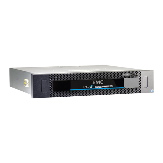
This document describes how to replace a faulted input/output (I/O) module in a DPE (disk
processor enclosure).
The I/O module resides on the SP printed circuit board (CPU board). To replace a faulted
I/O module, you must remove the SP assembly from the enclosure, and then remove its
cover to gain access to CPU board components.
You access an I/O module from the rear of the enclosure.
NOTICE
Always replace an I/O module with one that is the exact same type. Verify the type by
reading the label on the I/O module handle.
NOTICE
This procedure involves storage processor (SP) reboots coordinated to ensure that at least
one SP is running at all times. During an SP reboot, data will be unavailable to front- or
back-end connections that are not duplicated on the peer SP.
Before you
start..........................................................................................................2
l
Handling I/O
modules................................................................................................2
l
Replacing the faulted hardware
l
Returning a faulted
part........................................................................................... 12
l
component............................................................... 5
Advertisement

Subscribe to Our Youtube Channel
Summary of Contents for EMC VNXe
- Page 1 ® ® VNXe Replacing an input/output module in a disk processor enclosure 302-000-207 REV 02 July, 2015 This document describes how to replace a faulted input/output (I/O) module in a DPE (disk processor enclosure). The I/O module resides on the SP printed circuit board (CPU board). To replace a faulted I/O module, you must remove the SP assembly from the enclosure, and then remove its cover to gain access to CPU board components.
-
Page 2: Before You Start
Wrap the ESD wristband around your wrist with the metal button against your skin. If a tester is available, test the wristband. If an emergency arises and the ESD kit is not available, follow the procedures in Emergency procedures (without an ESD kit) on page EMC VNXe... - Page 3 Replacing an input/output module in a disk processor enclosure Emergency procedures (without an ESD kit) In an emergency when an ESD kit is not available, use the following procedures to reduce the possibility of an electrostatic discharge by ensuring that your body and the subassembly are at the same electrostatic potential.
- Page 4 Handle a replaceable unit gently. A sudden jar, drop, or vibration can permanently damage some replaceable units. Avoid touching any exposed electronic components and circuits on the replaceable unit. Never use excessive force to remove or install a replaceable unit. Take time to read the instructions carefully. EMC VNXe...
- Page 5 Replacing an input/output module in a disk processor enclosure Store a replaceable unit in the antistatic bag and the specially designed shipping container in which you received it. Use the antistatic bag and special shipping container when you need to return the replaceable unit. Replaceable units must acclimate to the operating environment before applying power.
- Page 6 Preparing the storage processor (SP) for service To protect your VNXe system from accidental data loss during this maintenance activity, you must prepare the SP for service. You prepare an SP for service by putting it in Service mode.
- Page 7 Replacing an input/output module in a disk processor enclosure NOTICE DO NOT REMOVE an SP assembly while the "Unsafe to remove SP" LED shown below is lit. Refer to Figure 3 on page 7 while performing the procedure that follows. Procedure 1.
-
Page 8: Removing The I/O Module
Procedure 1. Lift the blue latch carefully until it ejects the I/O module from the connector. 2. Lift the module out and away from the SP assembly and place it on a static free surface. EMC VNXe... -
Page 9: Installing The I/O Module
Replacing an input/output module in a disk processor enclosure Figure 5 Removing the I/O module CL5237 Installing the I/O module Refer to Figure 6 on page 10 while performing the procedure that follows. Procedure 1. Angle the I/O module slightly so it fits into the canister and align it with the blue and gray alignment pins. - Page 10 1. Pull out the latches on each side of the SP assembly and make sure they stay in the open position. 2. Align the SP assembly with the enclosure opening and push it straight into the enclosure. The latches begin to close when they contact the enclosure edges. EMC VNXe...
- Page 11 Replacing an input/output module in a disk processor enclosure 3. Close the right and left latches to fully seat the SP assembly in the enclosure. An audible click indicates that the latches are secure. Figure 8 Installing an SP assembly CL5232 4.
- Page 12 Return a > > > Customer Replaceable Part to enter the EMC Online Support website. If your screen does not show the Return a customer replaceable part option, contact your service provider for instructions on what to do next. EMC VNXe...
- Page 13 2014-2015 EMC Corporation. All rights reserved. Published in USA. Published July, 2015 EMC believes the information in this publication is accurate as of its publication date. The information is subject to change without notice. The information in this publication is provided as is. EMC Corporation makes no representations or warranties of any kind with respect to the information in this publication, and specifically disclaims implied warranties of merchantability or fitness for a particular purpose.


Need help?
Do you have a question about the VNXe and is the answer not in the manual?
Questions and answers