Table of Contents
Advertisement
Quick Links
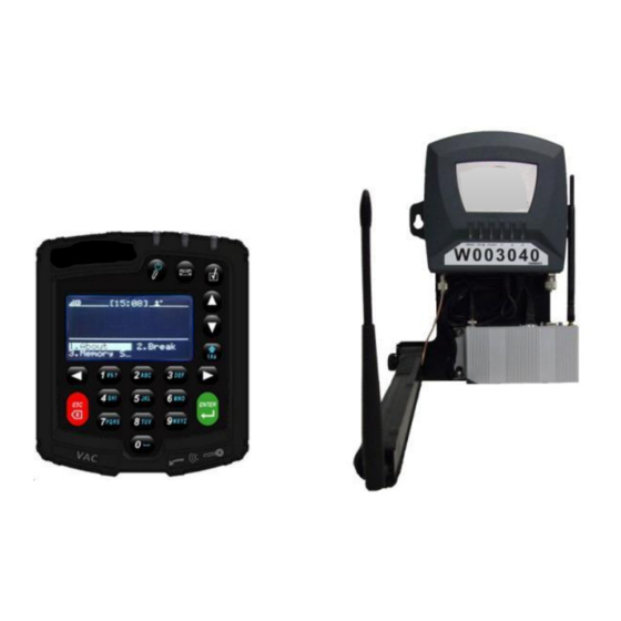
Enterprise VAC4 and VAC4S Hardware User's Guide
Enterprise Vehicle
Management System (VMS)
Hardware User's Guide
An operating and troubleshooting guide for the
VAC4, VAC4S, WAM, and other peripheral hardware
(some features require firmware from system release 08.05.00 or later)
123 Tice Blvd • Suite 101
©2020 PowerFleet Inc.
Woodcliff Lake, NJ 07677
Phone 201.996.9000 • Facsimile 201.996.9144
www.powerfleet.com
085-00000700 Rev K
085-00000700 Rev K
support@powerfleet.com
Page 2 of 100
Advertisement
Table of Contents
Troubleshooting

Related Manuals for PowerFleet VAC4S

Summary of Contents for PowerFleet VAC4S
- Page 1 Enterprise VAC4 and VAC4S Hardware User’s Guide Enterprise Vehicle Management System (VMS) Hardware User’s Guide An operating and troubleshooting guide for the VAC4, VAC4S, WAM, and other peripheral hardware (some features require firmware from system release 08.05.00 or later) 123 Tice Blvd • Suite 101 ©2020 PowerFleet Inc.
- Page 2 Communicator® (VAC), other vehicle peripheral hardware, and the Wireless Asset Manager (WAM). Safety The PowerFleet VMS is not intended for use as a primary safety device. Installation must NOT adversely affect any vehicle safety system or safety device. The installation, configuration and operational procedures provided in this Guide are intended for use ONLY by personnel certified on PowerFleet VMS installation.
-
Page 3: Table Of Contents
PowerFleet ® VAC4 and VAC4S Hardware User’s Guide CONTENTS INTRODUCTION ............................... 8 SECTION 1: SYSTEM OVERVIEW ..........................9 ............................9 OWER LEET NTERPRISE YSTEM IAGRAM VAC I : LCD, K , ID R ...........................10 NTERFACE EYPAD EADER AND Status Indicators ..................................10 ....................................14... - Page 4 PowerFleet ® VAC4 and VAC4S Hardware User’s Guide Checking VAC Synchronization Status ............................47 Reset VAC Synchronization ..............................48 Changing the VAC Facility ID ..............................49 Forcing the VAC to Low Power Mode (Hibernate) ........................49 Checking VAC Internal Backup Battery (not applicable for all VAC types) ................50 Changing the VAC Data Transmission Settings ........................51...
-
Page 5: Introduction
WAM * Wireless Asset Manager Related peripherals * WAM not required for Wi-Fi deployments. In addition to this guide, PowerFleet offers many other ways to learn the system including but not limited to: • Live training webinars • Interactive self-paced learning modules •... -
Page 6: Section 1: System Overview
PowerFleet ® VAC4 and VAC4S Hardware User’s Guide SECTION 1: SYSTEM OVERVIEW PowerFleet Enterprise System Diagram Hotspot Placement of a VAC on a vehicle • VAC must be mounted on the vehicle where it can be accessed by the operator without interfering with any vehicle operation. -
Page 7: Vac Interface: Lcd, Keypad, Id Reader And Leds
Yellow Note: When the Access, Message, and Checklist LEDs blink in sequence, the VAC is in ‘programming’ mode and cannot be used by operators. Call PowerFleet’s Support if this condition persists for more than twenty-five minutes. 085-00000700 Rev K support@powerfleet.com... - Page 8 PowerFleet ® VAC4 and VAC4S Hardware User’s Guide The VAC screen displays the current time, text, status icons (top row) and menu options. Some icons are described as follows: Icon Meaning Indication Reception bars provide an indication of signal strength the VAC is currently...
- Page 9 PowerFleet ® VAC4 and VAC4S Hardware User’s Guide The VAC indicates different vehicle and VMS system conditions in the main screen using text as well as iconography (some with animation). Common icons include the following: Icon Meaning Indication The Hourglass icon: Battery New battery request is being processed.
- Page 10 PowerFleet ® VAC4 and VAC4S Hardware User’s Guide Common icons include the following: Icon Meaning Indication The Low Battery icon: Battery The vehicle battery is low and requires a charge. The Engine icon: Low Oil Pressure High Engine The oil pressure or engine temperature inputs (VIMs 10 and 11) are outside the Temperature normal range.
-
Page 11: Menu Screens
PowerFleet ® VAC4 and VAC4S Hardware User’s Guide Menu Screens The Menu screens allow the operator to read and scroll through multiple lines of text as well as rapidly scan through and select the menu item of choice. Scroll indicator vertical bar... -
Page 12: Data Input Screens
PowerFleet ® VAC4 and VAC4S Hardware User’s Guide Data Input Screens Data input screens allow the operator to enter data when prompted by the VAC system. Scroll indicator vertical bar Up and Down ARROW keys scroll through available rows Status Header... -
Page 13: Multiple Choice Selection Screens
PowerFleet ® VAC4 and VAC4S Hardware User’s Guide Multiple Choice Selection Screens Multiple choice selection screens allow the operator to pick one item from a list which is similar to a pick list. Scroll indicator vertical bar Up and Down ARROW keys... -
Page 14: Login Methods (Various Methods Are Based On Which Version Of Powerfleet Is Purchased)
Alternatively, operator profiles can be added directly to the software (in “Any ID” mode or “Registered ID” mode) by presenting the access IDs to the desktop Access ID Reader. Refer to the PowerFleet Vision Pro training video for more details. -
Page 15: Section 2: Configuring The Hardware
LED is displayed. (Note: instructions for testing the BLU wire connection prior to VAC configuration are in Section 5). Once the PowerFleet Enterprise vehicle hardware has been properly installed, the vehicle can only be accessed using the yellow maintenance IDs, or a Maintenance level operator login. When a Maintenance operator logs in, they will be required to follow a series of VAC screen display instructions displayed to verify the installation and configuration. -
Page 16: Wi-Fi Configuration On The Vac
Server Port must be entered and a selection made for TLS encryption (TLS encryption or Proprietary as coincides with you software). For IDSY-hosted systems, this information is provided by PowerFleet. Note: If steps 4 through 6 are not performed in the proper order, the VAC will not connect to the server of access point. - Page 17 PowerFleet ® VAC4 and VAC4S Hardware User’s Guide 7. From the VAC menu screen, select CONNECT. 8. Connect to the facility’s wireless network. a. If the VAC display lists the desired SSID, use the up and down scroll arrows keys to select the desired SSID from the list.
-
Page 18: Wirelessly Receiving Credentials From A Nearby Wi-Fi-Configured Vac
PowerFleet ® VAC4 and VAC4S Hardware User’s Guide Wirelessly receiving credentials from a nearby Wi-Fi-configured VAC 1. Select a VAC that has been configured with the desired Wi-Fi profile. 2. Log into the VAC as a Maintenance operator or IT operator. -
Page 19: Receiving Credentials From A Wireless Asset Manager (Wam)
PowerFleet ® VAC4 and VAC4S Hardware User’s Guide Receiving credentials from a Wireless Asset Manager (WAM) 1. Log into PowerFleet Vision Pro software. 2. Access the System Configuration module by selecting the Settings icon in the top right frame. 3. Select “System Settings”. - Page 20 PowerFleet ® VAC4 and VAC4S Hardware User’s Guide 11. Click Sync in the top right frame. Wait 15 seconds for the synchronization to complete. The VAC will automatically synchronize the Wi-Fi profile(s) entered when in wireless communication range of the WAM.
-
Page 21: Vac Synchronization
There are 3 steps to achieving a functional impact management system once the impact sensor is properly physically installed. Refer to the PowerFleet Installation Guide. Each step is automatic and designed to work out-of-the-box. The first step is calibrating the impact sensor, which relies on proper installation and mounting. - Page 22 The system defaults to recommended settings for impact severities. However, to provide end users flexibility of use, each Impact Severity Level can be adjusted in the PowerFleet Vision Pro software. Select the Edit icon (the Edit button in the bottom of the screen) Impact Severity Levels may need to be manually adjusted if, for example, a vehicle is experiencing many Medium impacts, but operators are not reporting any damage on the self-inspection checklists triggered by those impacts.
-
Page 23: Reading Vac "Info" Screens
PowerFleet ® VAC4 and VAC4S Hardware User’s Guide Reading VAC “Info” Screens Screen Display (first page) Without logging in with an ID and password, Select INFO. IRF frequency for location data Vehicle ID Facility ID (or facility name code once synchronized) - Page 24 00, 02, 10, 12 PIB is currently highest priority 01, 03 DB is currently highest priority SH is currently highest priority Note: Other combinations are possible, contact PowerFleet Support for more details. 085-00000700 Rev K support@powerfleet.com Page 27 of 103...
-
Page 25: Section 3: Standard Operators
PowerFleet ® VAC4 and VAC4S Hardware User’s Guide SECTION 3: STANDARD OPERATORS Logging into the VAC (to start the vehicle) If the VAC screen is blank, press the VAC’s POWER button and turn the vehicle ignition key to the on position. -
Page 26: Login Error Code Table ["Error (Axx)" Plus Below Text When Login Is Attempted]
PowerFleet ® VAC4 and VAC4S Hardware User’s Guide Login Error Code Table [“Error (AXX)” plus below text when login is attempted] Code Display Text Possible Cause Solution Not authorized for The operator is not authorized in the system A Master or Maintenance operator can add this vehicle software for that vehicle. -
Page 27: Reading Vac "About" Screens
PowerFleet ® VAC4 and VAC4S Hardware User’s Guide Reading VAC “About” Screens The VAC’s “About” screen displays identifying information about the VAC’s current operator, registered license key, and system release version. To access the “About” screen from the VAC’s main login screen, select ABOUT. -
Page 28: Logging Off The Vac
PowerFleet ® VAC4 and VAC4S Hardware User’s Guide Logging Off the VAC To log off a vehicle, come to a complete stop with the vehicle (and turn off the engine, if applicable) . While stopped, press the VAC’s POWER button. -
Page 29: Answering Safety Checklists
PowerFleet ® VAC4 and VAC4S Hardware User’s Guide Answering Safety Checklists The VAC automatically prompts operators to answer mandatory safety checklists when the following occurs: 1. Compliance with established checklist rules must be enforced, A defined event, such as an impact, has occurred. - Page 30 PowerFleet ® VAC4 and VAC4S Hardware User’s Guide Note: If an operator tries to exit a checklist prior to completing all questions, the VAC screen will ask if the operator wants to exit the checklist. Exiting a checklist prior to completion will violate safety compliance...
-
Page 31: Critical Shutdown
PowerFleet ® VAC4 and VAC4S Hardware User’s Guide Critical Shutdown If an operator enters a checklist response that has been defined as “critical,” prior to completing the checklist, they will be prompted to confirm that they wish to complete the checklist with at least one critical response. If the operator confirms the critical response, the checklist is completed, the operator is automatically logged off, and the vehicle is locked out. -
Page 32: Operating The Vehicle
PowerFleet ® VAC4 and VAC4S Hardware User’s Guide Operating the Vehicle Break Mode The VAC’s “Break” option is available to all operators. This function allows an operator to reserve his/her vehicle for short periods of time (The default time is 15 minutes). -
Page 33: Motion Safety Feature
PowerFleet ® VAC4 and VAC4S Hardware User’s Guide Motion Safety Feature The VAC’s display and keypad are inoperable and log-off is prevented for Standard and Master operators when vehicle motion is detected. This safety feature prevents Standard and Master operators from interacting with the VAC while the vehicle is moving. -
Page 34: Section 4: Master Operators (Supervisors)
PowerFleet ® VAC4 and VAC4S Hardware User’s Guide SECTION 4: MASTER OPERATORS (SUPERVISORS) A Master operator (or a Maintenance operator) can log into any unlocked and certain locked vehicles at any time regardless of group assignments. In addition, a Master operator (or a Maintenance operator) can perform the following... - Page 35 PowerFleet ® VAC4 and VAC4S Hardware User’s Guide To temporarily authorize an operator on a vehicle, a Master or Maintenance operator must perform the following: Log into the vehicle to be temporarily assigned. 2. On the first menu screen, select the ACCESS.
-
Page 36: Clearing Event Lockouts
PowerFleet ® VAC4 and VAC4S Hardware User’s Guide Clearing Event Lockouts High and Severe impacts, failure to complete a safety checklist in the defined period (non-compliance), and checklist critical responses will shut down the vehicle and lock it out, to prevent Standard operators from using that vehicle. -
Page 37: Checklist Administration
PowerFleet ® VAC4 and VAC4S Hardware User’s Guide Checklist Administration Should the need arise, the VAC provides the ability for a Master operator (or Maintenance operator) to adjust the current compliance parameters for a vehicle. As previously described, each operator is provided 20 minutes of login time to complete a safety checklist, when the vehicle is non-compliant. -
Page 38: Manual Vehicle Lock
PowerFleet ® VAC4 and VAC4S Hardware User’s Guide Manual Vehicle Lock In certain instances, (e.g. when a vehicle requires maintenance) it may be desirable to prevent all Standard operators from accessing a vehicle (typically called a lockout or tag-out). When a vehicle is locked, only a Master operator (or a Maintenance operator) can access and use that vehicle. -
Page 39: Section 5: Maintenance Operators
VAC Timer Reset After Completed PM Preventative Maintenance (PM) due dates are established automatically through the PowerFleet® Vision Pro™ software, based on vehicle activity hours tracked by the VAC. When a PM is complete, the VAC’s activity timer must be reset, so the next PM due date can be automatically determined. -
Page 40: Diagnostic Errors
PowerFleet ® VAC4 and VAC4S Hardware User’s Guide Diagnostic Errors The VAC has built-in intelligence to diagnose and report errors. In certain cases, these errors auto-correct themselves; in other cases, the errors must be resolved and then ‘cleared’. These diagnostic errors are based on operating parameters that may indicate the VAC is not operating properly. -
Page 41: Id Optional ('Soft' Bypass)
PowerFleet ® VAC4 and VAC4S Hardware User’s Guide ID Optional (‘Soft’ Bypass) A Maintenance operator can bypass the access control feature of the VAC via firmware, allowing anyone to operate a vehicle. This is called ID Optional mode (“soft bypass”). It is most typically used if there is a VAC problem that prevents authorized operators from accessing a vehicle. -
Page 42: Read Operator Identification
The VAC can be used to determine the access credentials programmed onto an operator’s ID (this can also be performed using the desktop reader and the PowerFleet® Vision Pro™ software). Determining the credentials of an ID is most commonly performed when an ID is found without an operator to claim ownership. -
Page 43: Replacing An Existing Vac
PowerFleet ® VAC4 and VAC4S Hardware User’s Guide Replacing an Existing VAC When a VAC needs to be replaced, a Maintenance operator can automatically configure the new VAC with the previous VAC’s settings, using the “CloneVAC” menu option. This eliminates the need to re-run the Install Wizard by wirelessly transferring all settings and meters from the previous VAC to the replacement VAC, based on the last reported data for the specified VAC ID number. -
Page 44: Checking Vac Synchronization Status
VAC has a newer firmware version than the VAC being replaced). In this case, a Maintenance operator must manually configure the replacement VAC as if it was a new vehicle installation, using the VAC’s Install Wizard. Refer to PowerFleet® Installation Guide. Wrong Version! The previous VAC had a significantly older version of firmware than the replacement VAC. -
Page 45: Reset Vac Synchronization
In certain troubleshooting scenarios, the VAC’s downloaded profile (operators, groups, checklists, etc.) may need to be reset in order to force a re-synchronization. The reset Authorization function can only be performed with an access code provided by PowerFleet Support. Select RESET. Enter access code. -
Page 46: Changing The Vac Facility Id
The facility ID entered in the VAC is the unique identifier that allows the VAC to communicate with the correct PowerFleet Vision Pro software database. The facility code is first entered during the VAC configuration process but can be updated at any time. From the VAC menu screen, perform the following steps: 1. -
Page 47: Checking Vac Internal Backup Battery (Not Applicable For All Vac Types)
The VAC screen provides the battery condition of Charged, Charging or Not charging: Charged Battery is fully charged. Battery is not fully charged, but it is charging correctly and Charging should be fully charged within 30 minutes. Battery is not charging correctly. Contact PowerFleet’s Support Not charging team. 085-00000700 Rev K support@powerfleet.com... -
Page 48: Changing The Vac Data Transmission Settings
PowerFleet ® VAC4 and VAC4S Hardware User’s Guide Changing the VAC Data Transmission Settings Maintenance operator must perform the following: 1. Log into the vehicle. 2. Select HARDWARE. 3. On the “Hardware” sub-menu, select ID+RF. Data Frequency, 4. On the “ID+RF” sub-... -
Page 49: Checking And Changing The Vac Usage Totals
PowerFleet ® VAC4 and VAC4S Hardware User’s Guide Checking and Changing the VAC Usage Totals Maintenance operator must perform the following: 1. Log into the vehicle. 2. Select HARDWARE. 3. On the “Hardware” sub-menu, select Usage Totals. 085-00000700 Rev K support@powerfleet.com... -
Page 50: Testing The Blu Wire Connection Prior To Vac Configuration
PowerFleet ® VAC4 and VAC4S Hardware User’s Guide Testing the BLU wire connection prior to VAC configuration (Not applicable for JPT, P-Plug and VDI cable installations) Per the installation instructions, installers need to measure voltage changes for connection points of the inputs required. -
Page 51: Understand And Manually Set "Motion" For Electric Vehicles
PowerFleet ® VAC4 and VAC4S Hardware User’s Guide Understand and Manually Set “Motion” for Electric Vehicles (Not applicable for JPT, P-Plug and VDI cable installations) The VAC installation and configuration wizard is always used for establishing motion and idle thresholds on a vehicle. In some cases, motion and idle values may need to be adjusted during troubleshooting. -
Page 52: Understand And Manually Set "Idling" For Internal Combustion Vehicles
PowerFleet ® VAC4 and VAC4S Hardware User’s Guide Understand and Manually Set “Idling” for Internal Combustion Vehicles (Not applicable for JPT, P-Plug and VDI cable installations) The VAC determines the state of the vehicle (engine off, idling or motion) by configuring two ‘engine off’ ranges based on voltage sampling of the “BRN”... -
Page 53: Understand And Manually Set "Motion" For Internal Combustion Vehicles
PowerFleet ® VAC4 and VAC4S Hardware User’s Guide Understand and Manually Set “Motion” for Internal Combustion Vehicles (Not applicable for JPT, P-Plug and VDI cable installations) The VAC determines the state of the vehicle (idling or motion) by configuring two ‘in neutral gear’ ranges based on voltage sampling of the “BLU”... -
Page 54: Current Vac Configuration ("States" Screen)
PowerFleet ® VAC4 and VAC4S Hardware User’s Guide Current VAC Configuration (“States” Screen) The VAC has up to 3 read-only status screens of current VAC configuration settings. The screen content is dependent on the VAC license key. Therefore, every VAC may not contain all of the following: 1. - Page 55 1 = currently active, X = feature disabled Note: See the following table for most common Activity assignments. Additional combinations are possible, contact PowerFleet’s Support if the value displayed is not shown). 085-00000700 Rev K support@powerfleet.com Page 58 of 103...
- Page 56 PowerFleet ® VAC4 and VAC4S Hardware User’s Guide ACTIVITY MOTION NONE MOTION ENGINE GEAR LIFT SEAT LOAD ASSIGNMENT 00000 00001 00002 00003 00004 00008 00009 00010 00012 00014 00018 00082 00084 00092 00094 02002 02004 04002 04004 0000A 0000B 0000C...
-
Page 57: Last Vac Configuration ("Insreport" Screen)
PowerFleet ® VAC4 and VAC4S Hardware User’s Guide Last VAC Configuration (“InsReport” Screen) Every time the BASIC or SENSOR wizard is completed, from the VAC menu screen, select HARDWARE. Select InsReport. The InsReport on the VAC screen display provides the detail of the last completed configuration parameter. - Page 58 PowerFleet ® VAC4 and VAC4S Hardware User’s Guide The items and description are as follows: Item Description Values Basic Install Status of the BASIC configuration wizard Passed, Failed VacID Vehicle ID entered during the BASIC wizard 1 - 65534 VTyp...
-
Page 59: Impact Sensor Troubleshooting
Note: There are 4 additional impact VAC screen displays with detailed readings and settings that can be accessed by scrolling down. PowerFleet Support may request information about the detailed readings and settings from those screens for remote troubleshooting. -
Page 60: Manually Enabling Impact Calibration
5. Select OK when the calibration is acceptable. Note: The ToggleLog option enables and disables (default) detailed impact sensor reading logs which will rapidly consume the VAC memory. The ToggleLog option should only be selected at the request of PowerFleet Support. Check Vehicle Battery Voltage Monitoring The vehicle battery charge state is monitored in terms of voltage using the vehicle cable’s RED (B+) wire. -
Page 61: Section 6: Wam Use And Troubleshooting
Once installed, the WAM (including its integrated modem) automatically communicates with both VACs and the PowerFleet Vision Pro system software. Normal operation does not require any further human interaction. Note: Wi-Fi deployments do not require WAMs, however they can be used as supplemental communication. -
Page 62: Wam Troubleshooting
WAM Troubleshooting As long as the WAM power is uninterrupted, a WAM will automatically self-diagnose and report any issues to the PowerFleet support team. The LEDs on a WAM (and its integrated modem) will also change status when issues are detected. -
Page 63: Cradlepoint Modem Leds Explained
• Complete a return merchandise authorization (RMA) form (Appendix A). • Call PowerFleet Customer Service for the RMA number. • Vehicles will continue to function while the WAM is being repaired/ replaced; however, no system configuration changes (e.g. adding operators) will be possible, and system data will only be stored, not available/ viewable, until an operable WAM is restored. -
Page 64: Section 7: Vac Troubleshooting
• Complete an RMA Request form (Appendix A). • Internal VAC Call PowerFleet Customer Service for the RMA number. • malfunction Only the VAC should be returned for analysis /repair; Once the VAC is removed, the system MUST be hard-bypassed to use vehicle. (see Appendix B for bypass instructions) 085-00000700 Rev K support@powerfleet.com... -
Page 65: Section 8: Sensor Hub Errors
PowerFleet ® VAC4 and VAC4S Hardware User’s Guide SECTION 8: SENSOR HUB ERRORS Pinout Diagram Sensor Hub LED Indicators LED State Meaning No LED Sensor Hub is not powered. Cycling RED-AMBER-GREEN Sensor Hub is powered but not working properly with the VAC. -
Page 66: Section 9: Self-Diagnostic Error Codes
The PowerFleet system automatically diagnoses system errors. Errors can be monitored using reports in PowerFleet Vision Pro software (Refer to the PowerFleet Vision Pro training video). In addition, existing errors are indicated on the VAC screen display with a message and icon (See below) when no one is logged in. Icons are also displayed in the screen status header when a Standard or Master Operators are logged into a vehicle. - Page 67 PowerFleet ® VAC4 and VAC4S Hardware User’s Guide Interpreting Error Codes The example below illustrates how to interpret a VAC error message on the screen when logged in as a Maintenance operator. The VAC screen message is displayed as follows: 00-Error Msg > 24 Hours (Refer to Hardware Guide) Error Msg >...
- Page 68 PowerFleet ® VAC4 and VAC4S Hardware User’s Guide 08-100% Motion Err (Refer to Hardware Guide) [FUNCTIONAL] The VAC is sensing 100% motion while no one is logged in (the vehicle is unassigned) and the vehicle is not in ID Optional mode.
- Page 69 PowerFleet ® VAC4 and VAC4S Hardware User’s Guide 10- 0% Motion (Refer to Hardware Guide) [SHUTDOWN] The VAC is hard-bypassed or external relay is not wired to prevent access when logged off. Possible Cause(s) Action • Verify that the “BLU” wire is connected to the proper traction (motion) sensing circuit.
- Page 70 VAC o Complete an RMA Request form (See Appendix A) o Call PowerFleet’s Customer Service for an RMA number. o Only the VAC should be returned for analysis/repair. o Once VAC is removed, the system MUST be hard-bypassed to use vehicle.
- Page 71 1 hour. time • Complete an RMA Request form (See Appendix A) • Call PowerFleet’s Customer Service for a return material authorization number (RMA#). • Only the VAC should be returned for analysis/ repair. Internal battery error •...
- Page 72 Impact sensor o Complete an RMA Request form (See Appendix A) installation o Call PowerFleet’s Customer Service for an RMA number. Only the Impact Sensor should be returned for analysis/repair. 20-Keypad PIC Err Contact IDSY [FUNCTIONAL] The VAC has detected an internal error...
- Page 73 ® VAC4 and VAC4S Hardware User’s Guide • Complete an RMA Request form (See Appendix A) • Call PowerFleet’s Customer Service for an RMA number. • Only the VAC should be returned for analysis/repair. Internal VAC Error • Once VAC is removed, the system MUST be hard-bypassed to use vehicle.
- Page 74 • Verify that other VACs synchronize with the system correctly by driving another vehicle near the Wireless Asset Manager (WAM) or Wi-Fi Access Point, waiting 2 minutes, then checking the “Vehicle Configuration Status” report in PowerFleet® Vision Pro™ software to verify Last Detected Date is the current date.
- Page 75 Wireless Asset Manager (WAM) or Wi-Fi Access Point, waiting 2 minutes, then checking the “Vehicle Configuration Status” report in PowerFleet® Vision Pro™ software to verify Last Detected Date is the current date. • If other VACs are synchronizing...
- Page 76 • If the VAC is not supplying 5.5 ± 0.5 VDC o Complete an RMA Request form (See Appendix A) o Call PowerFleet’s Customer Service for an RMA number. o Only the VAC should be returned for analysis/repair. o Once VAC is removed, system MUST be hard-bypassed to use vehicle.
- Page 77 PowerFleet ® VAC4 and VAC4S Hardware User’s Guide 29-RVS Motion Error (Refer to Hardware Guide) [SHUTDOWN] The VAC did not correctly detect reverse motion during the configuration wizard phase when asked to move the vehicle in reverse for three second.
- Page 78 PowerFleet ® VAC4 and VAC4S Hardware User’s Guide 30- FWD Motion Error (Refer to Hardware Guide) [SHUTDOWN] VAC does not sense consistent forward motion. Possible Cause(s) Action • Log in to the VAC as a Maintenance operator and re-run the configuration wizard Speeding during drive (see Section 2).
- Page 79 PowerFleet ® VAC4 and VAC4S Hardware User’s Guide 32-Seat Switch Error (Refer to Hardware Guide) [SHUTDOWN] Seat/deadman switch error occurred in VAC config. Possible Cause(s) Action • Run the installation wizard again. Ensure that you are not on the seat switch or dead man Accidental operator error switch when instructed while selecting “NEXT”...
- Page 80 PowerFleet ® VAC4 and VAC4S Hardware User’s Guide 35-Idle Motion Error (Refer to Hardware Guide) [SHUTDOWN] The VAC has detected an idle threshold that is not within the specified range of 20. Possible Cause(s) Action • Verify that the “BLU” wire is connected to the proper traction (motion) sensing circuit.
- Page 81 Verify that impact sensor is installed on the specified vehicle. If not, and it is uninstalled intentionally, then you must either re-run Install Wizard (to disable sensing at the VAC) or disable Impact Sensing for that vehicle using PowerFleet® Vision Pro™. •...
- Page 82 PowerFleet ® VAC4 and VAC4S Hardware User’s Guide 38-Access Relay Err (Refer to Hardware Guide) [SHUTDOWN] During the “disable access control” test, the VAC did not disable the engine as designed. Possible Cause(s) Action • ”2” and “4” wire Verify that the”2” and “4” connection points (and “6” and “8” for internal combustion...
- Page 83 • If the VAC is not supplying 5.5 ± 0.5 VDC o Complete an RMA Request form (See Appendix A) o Call PowerFleet’s Customer Service for an RMA number. o Only the VAC should be returned for analysis/repair. o Once VAC is removed, the system MUST be hard-bypassed to use vehicle.
- Page 84 • If the VAC is not supplying 5.5 ± 0.5 VDC o Complete an RMA Request form (See Appendix A) o Call PowerFleet’s Customer Service for an RMA number. o Only the VAC should be returned for analysis/repair. o Once VAC is removed, the system MUST be hard-bypassed to use vehicle.
- Page 85 Log into the VAC as a Maintenance operator Incorrect facility ID o Navigate to the Access > FacilityID screen o Enter the facility ID provided by PowerFleet Support • Could also be an Incorrect Server IP or Port; Verify this also Multiple facilities have •...
- Page 86 Complete an RMA Request form (See Appendix A) VAC malfunction o Call PowerFleet’s Customer Service for an RMA number. o Only the VAC should be returned for analysis/repair. o Once the VAC is removed, the system MUST be hard-bypassed to use the vehicle.
- Page 87 None for Operators. The VAC self-re-boots until the error is cleared. • Complete an RMA Request form (See Appendix A) • Call PowerFleet’s Customer Service for an RMA number. Intermittent or • Only the VAC should be returned for analysis/repair.
- Page 88 Wireless Asset Manager (WAM) or Wi-Fi Access Point, waiting 2 minutes, then checking the “Vehicle Configuration Status” report in PowerFleet® Vision Pro™ software to verify Last Detected Date is the current date. • If other VACs are synchronizing...
- Page 89 Wireless Asset Manager (WAM) or Wi-Fi Access Point, waiting 2 minutes, then checking the “Vehicle Configuration Status” report in PowerFleet® Vision Pro™ software to verify Last Detected Date is the current date. • If other VACs are synchronizing...
- Page 90 Verify that impact sensor is installed on the specified vehicle. If not, and it is uninstalled intentionally, then you must either re-run Install Wizard (to disable sensing at the VAC) or disable Impact Sensing for that vehicle using PowerFleet® Vision Pro™. •...
-
Page 91: Section 10: System Support Information
PowerFleet ® VAC4 and VAC4S Hardware User’s Guide SECTION 10: SYSTEM SUPPORT INFORMATION Technical Specifications – VAC4S and VAC4 Electrical Specifications Power Interface Nominal Rated, operating supply voltage (VDC) – I/C or Electric Internal Fuse (A) [non-serviceable] External In-Line Fuse (A)** **Pre-installed in wiring harness;... -
Page 92: Communication Specifications
PowerFleet ® VAC4 and VAC4S Hardware User’s Guide Communication Specifications Intelligent RF Protocol Nominal Frequency (MHz) - US 902.6 927.4 Frequency (MHz) - EU 868.3 868.3 869.85 250*** (US) Output power (mW) 500*** (EU) Modulation FSK, DTS, Narrow band Frequency Agility 26 Adjustable channels (US) 868.3, 868.95, 869.525, or 869.85 MHz (EU) -
Page 93: User Interface Specifications
Reader Location External/Bottom edge mount Proximity Card Specification Proximity Card Type HID only (VAC4) or Multi-Prox (50+ protocols; 125 KHZ or 13.65 MHz – VAC4S) Proximity Reader Location Internal / tamperproof Mounting Specifications Specification Electrical considerations Isolation from chassis required (and provided) -
Page 94: Regulatory And Product Certifications
PowerFleet ® VAC4 and VAC4S Hardware User’s Guide GPS Receiver Specification Manufacturer Details US Global Sat model BR-355-S4 Chipset / Protocol SiRF Star IV / NMEA 0183 (default) or siRF binary (alternate) Accuracy Less than 2.5 m ( < 8.2 ft) 2D RMS SBAS Enabled Acquisition rate (averages) Hot start = 1 sec;... - Page 95 PowerFleet ® VAC4 and VAC4S Hardware User’s Guide Environmental Specifications Specification Operating Temperature* -40 C to +85 C (screen not visible below -32 C) Storage Temperature* -40 C to +85 C Humidity MIL-STD-810F, Method 507.4, 95% RH (non-condensing) Environmental Sealing Exceeds NEMA 3R, Mil-Std-810E Method 506.3 Procedure III;...
-
Page 96: Customer Support And Return Merchandise Authorization (Rma) Policy And Procedures
Step 3: Evaluation and Damage Description • In the event the repair requires a purchase order to proceed, PowerFleet will send the quotation for repair to the PO approver (identified in Step 1). The RMA hardware will remain on hold until the PO approver provides additional direction. -
Page 97: Appendixa (Rma Request Form )
Vehicle Type (Forklift, Vehicle Number Make Model driven? Pallet Jack, Reach, etc.) Ship the secured packaged hardware to the following address: VIP Industries, PowerFleet RMA Department, 90 Brighton Road, Clifton NJ 07012 085-00000700 Rev K support@powerfleet.com Page 100 of 103... -
Page 98: Appendix B (Hard-Bypass Powerfleet® Access Control)
Refer to the PowerFleet® Installation Guide for detailed wiring diagrams. Hard-bypassing access control You must open the vehicle and have access to the PowerFleet® relay circuit to complete this procedure. Depending on the access control relay you are using, the connection points may differ: For relays with embedded spade terminals: a. -
Page 99: Appendix C (Using The Powerfleet Wi-Fi Test Tool)
PowerFleet ® VAC4 and VAC4S Hardware User’s Guide Appendix C (Using the PowerFleet Wi-Fi Test Tool) POWERFLEET'S WI-FI TEST TOOL. THERE ARE TWO TEST TOOLS AVAILABLE. THE SMART PHONE APP (SEARCH "VMS TOOLS" IN THE ITUNES OR GOOGLE PLAY APP STORES) IS THE PREFERRED METHOD. A PC-BASED VERSION IS ALSO AVAILABLE THROUGH THE I.D. SYSTEM CUSTOMER PORTAL (or email support@powerfleet.com). - Page 100 IT should verify the AP logs, firewalls, etc. to confirm why the connection cannot be reached. Please send a screen capture of the successful or failed test screen to PowerFleet Support: support@powerfleet.com for immediate or future troubleshooting purposes (The subject of the email should be “WiFi test tool results”).
Need help?
Do you have a question about the VAC4S and is the answer not in the manual?
Questions and answers
Upper left hand corner of VAC4 display has a set of forks with a flashing check mark
A flashing check mark with a set of forks in the upper left-hand corner of the PowerFleet VAC4 display indicates that there is a checklist that needs to be completed.
This answer is automatically generated
where are the install instructions for Vac4S cortex m4. Install is for electric forklift.
The installation instructions for the PowerFleet VAC4S are included in the VAC4 and VAC4S Hardware User’s Guide. While the guide does not provide precise instructions for each specific vehicle model, including electric forklifts, it offers basic knowledge needed for a certified installer. The VAC must be mounted where the operator can access it without interfering with vehicle operation, and it connects to the vehicle using an 18-foot cable harness. Installation should be done by authorized, certified personnel following proper safety protocols.
This answer is automatically generated
Instalación Guide
The installation guide for the PowerFleet VAC4S includes the following key steps:
1. Certified Personnel Only: Installation must be done by personnel certified on PowerFleet VMS installation, using proper tools and safety protocols.
2. VAC Configuration:
- A Maintenance operator must configure the VAC using the BASIC configuration wizard before the vehicle can be used by Standard or Master operators.
- The configuration process includes confirming or entering the Facility ID and following on-screen instructions.
- This process takes about 3 to 5 minutes.
3. Sensor Installation:
- Use the Sensor Install Wizard and ensure the “Output Alert” feature is assigned to VIM Wizard selection “107.”
- Confirm the output alert works on the ‘External Indicator’ screen.
- Ensure the Sensor Hub is connected to the VAC (connector C102) and the sensor cable is connected to the VIM6/7 port.
- Check RED and BLACK wires are properly connected to the sensor or relay.
- Verify the Sensor Hub LED is orange or green to confirm it is working.
4. Troubleshooting and Repairs:
- If sensors fail or the Sensor Hub is damaged, complete an RMA Request form.
- Only the VAC should be returned for analysis or repair.
- The system must be hard-bypassed to use the vehicle without the VAC. Follow instructions in Appendix B for hard-bypass.
These steps summarize the installation and configuration process for the VAC4S system.
This answer is automatically generated