Advertisement
Quick Links
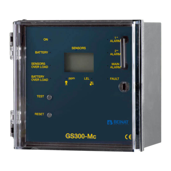
Control Unit from 1 to 3 Conventional sensors GS300-Mc
The GS300-Mc control unit has been designed and built according to European regulations to flexibly detect the
presence of toxic and/or explosive gas and OXYGEN, through the connection of 3 remote probes.
A microprocessor is used to create a complete surveillance and control system with maximum flexibility. Thanks to this
and its other features GS300-Mc is suitable for civil use, industrial use and small underground car parks.
The GS300-Mc control unit has three danger levels:
st
st
1
LEVEL, 1
Alarm. This was set to 8 % of L.E.L. (120ppm)
nd
nd
2
LEVEL, 2
Alarm. This was set at 13% of L.E.L. (200ppm)
rd
3
LEVEL, Main Alarm. This was set at 20 % of L.E.L. (300ppm)
For oxygen the centrol unit GS300-Mc presents three levels of danger which are:
1st Pre-Alarm. Both in deficiency and excess of Oxygen.
2nd Pre-alarm. Both in deficiency and excess of Oxygen.
Main alarm. Both in deficiency and excess.
To facilitate event readings, the control unit has a front panel with 4 LEDs indicating which probe is currently being
monitored in rotation, and a display showing the gas concentration measured.
Other technical features make this control unit extremely versatile and reliable; for example, by using a series of micro-
switches it is possible to:
Select or disable the probe when not installed or faulty;
Select the type of gas to be detected (toxic or explosive);
Choose the relay functioning mode (pulsed or continuous);
Choose to enable or disable of the intrinsic safety.
The GS300-Mc has the prerequisite to be able to test "TEST" in two different ways:
1) System Test TEST. Pressing the TEST button tests the entire system, including the relays and accessories connected
to it.
2) Maintenance TEST. With special arrangements (see page 8) you can enable the function of:
Exclusion of the general alarm relay for a maximum duration of 60 minutes.
The IP44 external structure was designed for installations on walls, or on electrical panels by means of special brackets.
In addition to the alarm signal light, it is fitted with an internal buzzer.
Important: Assembly / maintenance of the appliance must be carried out by qualified personnel and in
accordance with applicable laws and regulations.
The manufacturer assumes no responsibility for the use of products that have to comply with particular
environmental and / or installation standards.
Important note
Before connecting the equipment, it is recommended that you read the instruction manual carefully and keep
it for future reference. It is also recommended to perform the electrical connections correctly as per enclosed
drawings, observing the instructions and the Standards.
N.B. Refer to the documentation in all cases where the symbol is on the side
Installation
and user guide
CONFORMITY
INSTALL IN SAFE
AREA, NO
ATEX
Electric connections also available on
Belonging
EN 50194
EN 45544-1-3
EN 50270
EN 61010-1
Compliant EN 60079-29-1
Installation EN 60079-29-2
Reports issued by TUV Italia
Channel: Beinat gas solutions
to
Rev. 6
Advertisement

Summary of Contents for BEINAT GS300-Mc
- Page 1 Control Unit from 1 to 3 Conventional sensors GS300-Mc Rev. 6 The GS300-Mc control unit has been designed and built according to European regulations to flexibly detect the presence of toxic and/or explosive gas and OXYGEN, through the connection of 3 remote probes.
-
Page 2: Maintenance
TERMS and EXPECTATIONS: The installation of the GS300-Mc probe, its ordinary and extraordinary maintenance, and its out of service removal at the end of the functional life guaranteed by the manufacturer, must be carried out by authorized and/or specialized personnel. - Page 3 Zone 2 - Mixed IP66 ATEX: High probability of escape, high risk locations, premises for which applicable regulations apply. Zone 1 - Hazardous Area, High Risk Hazards, Rooms for Which Regulations, Tanks, Control Valves are in force. 1 0 8 1 4 4 1 2 3 GS300-Mc 1 4 0 Screws5 ma Brackets Page 3...
- Page 4 The numbers in the rectangle “1 2 3 “: are the probe connected; They lidht up in sequence and identify the monitored zone. e) The timing symbol lights when GS300-Mc is in warm up phase, the same time its begins the count down Page 4...
-
Page 5: Important Note
Components and Commands continue 11) DISPLAY. The display below is represented with all its segments and indications a) The number on the display indicates the concentration of gas detected. b) The number drawn on the display indicates which probe is monitored The exchange of data of every connected probe is every about 4 seconds. - Page 6 Electrical Connections WARNING. Before connecting to the mains power, ensure the voltage is correct. Carefully follow the instructions and the connections according to Regulations in force, keeping in mind that the signal cables should be laid separate from the power cables. An automatic cut-off switch (appropriately identified as devicesectioning of the detector) should be incorporated in the electrical system, adequatelylocated and easily accessible.
- Page 7 Control unit power supply and connection of a solenoid valve with sirens to 12 VDC trough an alternative source and recharge battery. It's not possible to connect directly solenoid Solenoid valve GAS and Sirens 12 VDC valves or sirens 12V.dc. to the GS300-Mc Diode Probe 1 Probe 2...
- Page 8 Zo nes . You can connect 3 probes to the GS300-Mc. The control unit is tested with the probes connected In some installations, you may need only one probe. In this case we will proceed to disable a probe, to do this select the switch of the probe (zone) concerned.
- Page 9 In the ON position, the positive safety function is enabled. The relay is energized after performing the waiting phase and switches when the GS300-Mc is in main alarm In the OFF position, the positive safety function is disabled. The relay is energized only when the GS300-Mc enters the state of main alarm Switch 2 –...
- Page 10 The Sensor must be selected with an IP degree depending on the area to be controlled (Kitchens, Boiler Rooms, Laboratory, etc.) by selecting one of the probes from Beinat from IP30 to ATEX. see page 3 Position of the detection sensors You can connect many types of remote probes to this unit.
- Page 11 The control unit gives a max current of 100mA. Check the connection design. If othe r p roble ms arise, a sp ecialised and /or authorise d te chnician and/or the Dis tributor of BEINAT S.r.l. should be contacted directly. Page 11...
-
Page 12: Disposal Of Old Electrical & Electronic Equipment
Dealer stamp Purchase date: Serial number: Beinat S.r.l. following the purpose of improving its products, it reserves the right to modify the technical, aesthetic and functional characteristics at any time and without giving any notice. BEINAT S.r.l. Via Fatebenefratelli 122/C 10077, S. Maurizio C/se (TO) - ITALY Tel.
Need help?
Do you have a question about the GS300-Mc and is the answer not in the manual?
Questions and answers
How do you reset service light?