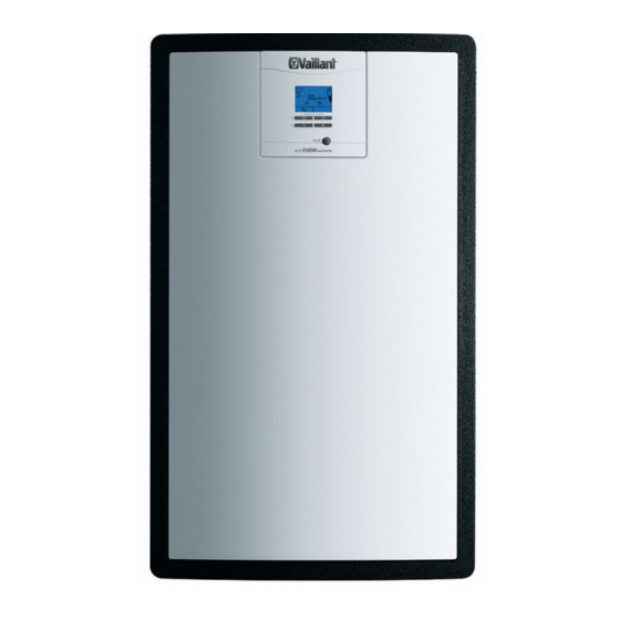
Vaillant auroFLOW plus VPM 15 D Installation And Maintenance Instructions Manual

Vaillant auroFLOW plus VPM 15 D Installation And Maintenance Instructions Manual

Table of Contents

Advertisement

Quick Links

For the competent person
Installation and maintenance instructions
Publisher/manufacturer
Vaillant GmbH
Berghauser Str. 40
D-42859 Remscheid
Tel. +49 21 91 18‑0
Fax +49 21 91 18‑2810
info@vaillant.de
www.vaillant.de
Installation and maintenance instructions
auroFLOW plus
VPM 15 D, VPM 30 D, wiring centre
BE (de), DE

Advertisement

Table of Contents
loading

Summary of Contents for Vaillant auroFLOW plus VPM 15 D

  • Page 1 Installation and maintenance instructions For the competent person Installation and maintenance instructions auroFLOW plus VPM 15 D, VPM 30 D, wiring centre BE (de), DE Publisher/manufacturer Vaillant GmbH Berghauser Str. 40 D-42859 Remscheid Tel. +49 21 91 18‑0 Fax +49 21 91 18‑2810 info@vaillant.de www.vaillant.de...
  • Page 2: Table Of Contents

    Contents Contents Test menu............23 Configuration ............23 Safety ..............3 Documenting start-up .......... 24 Action-related warnings ......... 3 Handing over to the operator ......24 Troubleshooting ..........25 Intended use ............3 10.1 Querying the fault memory ........25 General safety information ........
  • Page 3: Safety

    1.3.2 Risk of death due to lack of safety The product is designed for use in solar sys- devices tems. The Vaillant solar system is used for solar heating support or hot water genera- The schematic drawings included in this doc- tion.
  • Page 4 1 Safety ▶ Check that there is no voltage. 1.3.7 Risk of material damage caused by using an unsuitable tool 1.3.4 Risk of death due to over-voltage ▶ Use the correct tool to tighten or loosen During a storm, components such as solar screw connections.
  • Page 5: Requirements For Lines

    Safety 1 1.3.12 Product fault as a result of incorrect Sensor and bus lines must not run parallel to system pressure 230 V lines over a length of more than 10 m. ▶ The supply lines must be laid separately. To avoid operating the system with too little ▶...
  • Page 6: Notes On The Documentation

    2 Notes on the documentation Notes on the documentation System conditions The following conditions must be met by the solar system to Observing other applicable documents ensure correct operation: ▶ You must observe all the operating and installation in- – The solar charger must be installed below the collector structions included with the system components.
  • Page 7: Design Of The Auroflow Plus Solar Charger (Basic Module Only)

    Product description 4 Design of the auroFLOW plus solar charger (basic module only) Solar return – 3/4" sleeve (flat-sealing) Solar fluid storage tank Cylinder charging circuit automatic air vent Retainer for front casing screw Cylinder return temperature sensor Solar controller Cylinder charging pump Solar circuit safety temperature monitor Cylinder charging circuit flow sensor...
  • Page 8: Design Of The Auroflow Plus Solar Charger (Basic Module And Expansion Module)

    4 Product description Design of the auroFLOW plus solar charger (basic module and expansion module) Note The functional elements of the basic module are described on the previous page. 2. Solar fluid storage tank 2. Solar pump Installation and maintenance instructions auroFLOW plus 0020149486_04...
  • Page 9: Information On The Identification Plate

    Installation 5 Installation Information on the identification plate The identification plate is mounted on the underside of the Storage conditions product in the factory. The identification plate contains the ▶ following information: Store the product in a dry and dust-free room. Information on the identi- Unpacking the product Meaning...
  • Page 10: Product Dimensions And Connection Dimensions

    5 Installation Product dimensions and connection Installation clearance dimensions 150 mm (better: 200 mm 350 mm) 450 mm 200 mm ▶ When using the accessories, observe the minimum clear- ances/installation clearances. Note There must be a clearance of at least 150 mm above and below the product.
  • Page 11: The Rules For Laying The Pipelines For The Solar Circuit Must Be Followed

    Installation 5 5.11 The rules for laying the pipelines for the 5.12.2 Wall-mounting the basic module of the solar circuit must be followed solar charging system ▶ To prevent energy loss, all pipelines of the solar and cyl- Danger! inder charging circuit must be fitted with heat insulation. Risk of accidents as a result of insuffi- ▶...
  • Page 12: Installation

    Connecting the discharge line to the safety ▶ group Avoid mechanical tension on supply lines. Note An empty Vaillant solar fluid container can be Caution. used as a collecting container. Risk of material damage due to heat trans- fer during soldering.
  • Page 13: Carrying Out The Electrical Installation

    If a UV5 shift-load switching valve is included in the hydraulic scheme, we recommend that you use a 3-way valve from the Vaillant range of ac- cessories and connect this using the connection cable that is also available as an accessory.
  • Page 14 6 Installation ▶ Connect the product using a fixed connection and a partition with a contact opening of at least 3 mm (e.g. fuses or power switches), see Mains connection cable (→ Page 10). 6.2.3 Connecting the collector temperature sensor, cylinder temperature sensor and eBUS system controller Note...
  • Page 15: Completing Installation

    Installation 6 Completing installation 6.4.2 Removing the storage tank 6.3.1 Checking the electrical installation ▶ Following installation, check the electrical installation to ensure that all connections are fitted properly and are sufficiently insulated. 6.3.2 Installing the front casing Fit the front casing from the front up to the stop. Make sure that no cables are pinched or in contact with hot components and that the solar control is locked in place in the opening.
  • Page 16: Installing The Second Solar Pump

    6 Installation 6.4.4 Fitting the controller bracket ▶ Slide the controller bracket (1) over the pipes until it clicks into place. Installing the second solar pump 6.5.1 Connecting the hydraulic lines of the second solar pump Cut two openings for the connection pipes at the points provided in the side section of the basic module casing.
  • Page 17 Installation 6 Connect the second solar pump (6) and the pipe set (5, Undo the four bolts (1). 7) using flat seals. Open the controller casing. – The arrow on the pump casing must point in the Remove the dummy plugs (2). direction of the long pipe (5).
  • Page 18: Wall-Mounting The Expansion Module

    7 Operation 7.1.1 Calling up the installer level Tighten the bolts (1). 10. Attach the power cable to the pipe using the clip sup- Caution. plied. Make sure, however, that the power cable is not positioned flush to the pipe. Risk of damage caused by incorrect hand- ling.
  • Page 19: Filling And Purging The System

    The use of unsuitable solar fluid may cause malfunctions and damage to the solar sys- tem. ▶ Use only Vaillant solar fluid. Note To enable simple filling of solar fluid, we recom- mend the mobile filling device. Protect live components against escaping water.
  • Page 20: Running Through The Installation Assistant

    – Cascade: No: 1 basic module + 1 expansion module, if required – Cascade: Yes: Several basic modules Fill the storage vessel with Vaillant solar fluid to mark 1 Note (1). If you have selected Cascade: Yes, you – Capture any solar fluid that is emitted from the pur- must then enter the number of the solar char- ging valve.
  • Page 21 Start-up 8 Press Conditions: The solar pump will continue to run. ▶ Once air has stopped being drawn in after a few 8.2.5 Filling the solar circuit seconds, close the purging valve. ▶ Each time the solar system starts up again, the solar pump Open the filling connection and drain the solar fluid until must run at increased power for a while until the solar line the fluid level reaches the '2' mark.
  • Page 22: Carrying Out Pressure Compensation

    Failure to purge the system or purging at a time other than the one specified, may cause damage to the solar system. Vaillant accepts no liability for the correct operation of the solar system in this instance.
  • Page 23: Test Menu

    Start-up 8 Test menu Configuration As well as the installation assistants, you can also call up the You can use the menu Configuration to subsequently test menu for start-up, maintenance and troubleshooting. change the settings that have been made using the installation assistant.
  • Page 24: Documenting Start-Up

    9 Handing over to the operator 8.5.3 Heating flow set target temperature are started up separately. During the first stage, only the lower solar pump is running. You can use the Compensa- Note tion time setting to adjust the length of the first stage. Set the compensation time so that the solar fluid level is approx- If a system controller is connected, this menu imately 5 cm in both storage tanks before the second solar...
  • Page 25: 10 Troubleshooting

    Troubleshooting 10 10 Troubleshooting Inspection and maintenance work Interval Check that the brackets and collector com- Annually 10.1 Querying the fault memory ponents are clean and fitted properly Menu → Installer level Fault list Check the pipe insulations for damage Annually Solar controller The product has a fault memory.
  • Page 26: Preparing Inspection And Maintenance Work

    Then completely fill the solar cir- 11.5.3 Adding solar fluid cuit. ▶ Add as much new Vaillant solar fluid as you have re- moved (Filling the storage tank (→ Page 19)). 11.5.1 Check solar fluid ▶ Check the solar fluid using an antifreeze tester or a re- 11.5.4 Carrying out pressure compensation...
  • Page 27: Completing Inspection And Maintenance Work

    Ensure that defective components are disposed of prop- ▶ Close all available isolator devices in the cylinder char- erly. ging circuit (on-site). ▶ Observe the applicable national regulations. 14 Customer service Applicability: Belgium N.V. Vaillant S.A. Golden Hopestraat 15 0020149486_04 auroFLOW plus Installation and maintenance instructions...
  • Page 28 14 Customer service B-1620 Drogenbos Belgien, Belgique, België Kundendienst / Service après-vente / Klantendienst: 2 3349352 Applicability: Germany Vaillant Profi-Hotline: 018 06 999120 (20 Cent/Anruf aus dem deutschen Festnetz, aus dem Mobilfunknetz max. 60 Cent/Anruf.) Installation and maintenance instructions auroFLOW plus 0020149486_04...
  • Page 29: Appendix

    Appendix Appendix Overview of the installer level menu structure Menu Information Basic settings Installer level Back Select Enter code Installer level Fault To delete the fault list List of faults press OK Test menu F.01 Configuration Back Back Back Select Back Delete Solar pump...
  • Page 30 Appendix Configuration Time Language Date 16:40 Time Back Select Back Configuration Summer/winter time Date Automatic Time clock change Summer/winter time Back Select Back Configuration Cascade Time Solar module cascade Summer/winter time available? Cascade Back Select Back Configuration Number of collectors Summer/winter time Cascade Number of collectors...
  • Page 31 Appendix Configuration Switch-on diff. UV5 switching temp. T5/T6 temperature Max. cylinder temp. differential Switch-on diff. Back Select Back Configuration eBUS controller Max. cylinder temp. Switch-on diff. Not detected eBUS controller Back Select Back Configuration Filling power Switch-on diff. eBUS controller Filling power Back Select...
  • Page 32: B Connection Diagram

    Appendix Connection diagram eBus flow STW1 STW2 eBus 230VAC Detecting and rectifying faults Fault Possible cause Explanation/remedy The pumps start up at irregular intervals, Blockage prevention function No fault including at night Collectors are warmer than the cylinder, Cylinder is charged No fault but the solar plant does not start or a forced pause of 10 minutes is activ-...
  • Page 33: D Technical Data

    Appendix Fault Possible cause Explanation/remedy Filling is completed, however fluid is not Excessive loss of pressure in the solar cir- Check the solar circuit for blockages/kinks, flowing back from the collectors cuit check the collector field for blockages, in- crease the filling time on the solar control Solar pump is running, however cylinder Temperature of the solar fluid is too low No fault...
  • Page 34 Appendix VPM 15 D basic VPM 30 D (ba- module sic module with expansion module) Product dimensions, 340 mm 340 mm depth ≤ 15 m² ≤ 30 m² Collector surface area ≤ 6 ≤ 12 Number of collectors Installation and maintenance instructions auroFLOW plus 0020149486_04...
  • Page 35: Index

    Index Index Regulations ................5 Removing the controller bracket.......... 15 Adding solar fluid..............19 Removing the front casing........... 11 Removing the storage tank ..........15 Article number ............... 6 Replacing the solar fluid ............26 Routing the mains connection line ........14 CE label .................
  • Page 36 Berghauser Str. 40 D-42859 Remscheid Telefon 021 91 18‑0 Telefax 021 91 18‑2810 Vaillant Profi-Hotline 018 06 999120 (20 Cent/Anruf aus dem deutschen Festnetz, aus dem Mobilfunknetz max. 60 Cent/Anruf.) Vaillant Kundendienst 018 06 999150 (20 Cent/Anruf aus dem deutschen Festnetz, aus dem Mobilfunknetz max. 60 Cent/Anruf.) info@vaillant.de www.vaillant.de...

This manual is also suitable for:

Auroflow plus vpm 30 d

Table of Contents