Table of Contents
Advertisement
Quick Links
Advertisement
Table of Contents

Related Manuals for SOMAS SKV


Summary of Contents for SOMAS SKV
- Page 1 Edition: 2020-10 Mi-706 EN Service and operating instruction Ball valves Type SKV/SKVT Nominal pressure Nominal size Type SKV PN 40 Class 300 DN 25 - 50 1 - 2 Type SKV PN 25 Class 150 DN 80 - 400 3 - 16...
- Page 2 We keep the right to do any technical changes which are necessary to improve the product without prior notice. Copyright Copyright by SOMAS Instrument AB. No part of this publication may be reproduced, stored in a retrieval system, or transmitted in any form or by any means, graphic, electronic, mechanical, photocopying, recording, taping, or otherwise without the prior permission of the copyright owner.
-
Page 3: Table Of Contents
Original document - Mi-706 EN Edition: 2020-10 Table of contents Preliminary remarks Explanation of warnings, symbols and signs 1.1.1 Warnings 1.1.2 Symbols and signs Safety Safety instructions 2.1.1 General dangers 2.1.2 Hazards due to electrical equipment 2.1.3 Additional hazards 2.1.4 State of the art 2.1.5 Preconditions for using the valve... - Page 4 Edition: 2020-10 Original document - Mi-706 EN Technical specifications Tightening torque for bolts 4.1.1 Torques for flange boltings 4.1.2 Tightening torque for screws in valves 4.1.3 Tightening torque for stuffing box gland 4.1.4 Tightening torque for bearing blocks Assembly Unpacking and transportation Installation of the valve in the pipeline 5.2.1 Important information for installation...
- Page 5 6.6.5 Disassembly, DN 450–500 valves 6.6.6 Cleaning, lubricating and mounting Adjustment of the end positions 6.7.1 Setting of the “closed” position with type SKV 6.7.2 Setting of the “open” position with type SKV Leak test of the valve Components 6.9.1 SKV, DN 25-50 6.9.2...
-
Page 6: Preliminary Remarks
Edition: 2020-10 Original document - Mi-706 EN 1 Preliminary remarks To enable you to find information quickly and reliably in the operation manual, this chapter familiarises you with the structure of the operating manual. This manual uses symbols and special characters which make it easier for you to find information. -
Page 7: Symbols And Signs
Original document - Mi-706 EN Edition: 2020-10 Note Advices and give tips for better understanding of the manual or a better handling of the valve. 1.1.2 Symbols and signs Symbols and signs are used in this operating manual to provide fast access to information. -
Page 8: Safety
Edition: 2020-10 Original document - Mi-706 EN 2 Safety Safety instructions 2.1.1 General dangers Sources of danger resulting in general hazards: • Mechanical hazards • Electrical hazards 2.1.2 Hazards due to electrical equipment Due to the permanent dampness, electrically-operated machine parts represent a potential source of danger. -
Page 9: State Of The Art
2.1.4 State of the art This product has been built by SOMAS Instrument AB in accordance with state- of-the-art standards and the recognized safety rules. Nevertheless, its use may constitute a risk to life and limb of the user or of third parties, or cause damage to the valve and to other material property, if: •... -
Page 10: Liability For Non-Designated Use
Replacing damaged parts Valve parts that are not in perfect condition must be replaced immediately with original spare parts! Use only original spare and wear parts from SOMAS Instrument AB. On unauthorized parts is not guarantee that they have been designed and manufactured according to the application. -
Page 11: Safety Instructions For Ball Valves
Original document - Mi-706 EN Edition: 2020-10 Safety instructions for ball valves • Operation of the ball valve is always subject to the local safety and accident prevention regulations. Danger! Risk of injury! Observe movements of the ball. Keep hands, tools and other objects away from the area where the ball moves when the actuator is connected to compressed air system. - Page 12 The ball valve may cause noise in the pipeline. The noise level depends on the type of application and can be determined with the SOMAS software SomSize. Additional noise sources in the vicinity of the ball valve may increase the noise level.
-
Page 13: Description
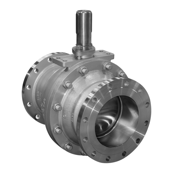
Function and design The SOMAS ball valve type SKV and SKVT is a full bore valve with a cylindrical bore for maximum capacity. The pressure rating for DN25 - 50 is PN50 and for DN80 - 500 it is PN25. The flanges comply with various standards and can be drilled according to the EN, ISO and ASME standards. -
Page 14: Technical Specifications
Edition: 2020-10 Original document - Mi-706 EN 4 Technical specifications Tightening torque for bolts 4.1.1 Torques for flange boltings Use washers and greased bolts to ensure that the joints function properly. Tighten the bolts alternately with a torque wrench. Suitable torque varies according to the size of the bolt. PN/Class Bolt Torque... -
Page 15: Tightening Torque For Screws In Valves
Original document - Mi-706 EN Edition: 2020-10 4.1.2 Tightening torque for screws in valves Screw dim./class Tightening torque MV 1) (Nm) 1) Mv-recommendations refer to flat burr-free surfaces lubricated with a good quality lubricant. 4.1.3 Tightening torque for stuffing box gland Screw dim./class Torques Graphite box (Nm) Torques PTFE box (Nm) -
Page 16: Assembly
Edition: 2020-10 Original document - Mi-706 EN 5 Assembly Unpacking and transportation Inspect the ball valve for transport damage when unpacking. The protective caps must only be removed immediately before assembly. The valve must be stored on a suitable base and protected against dirt until installed. The valve must be stored in a cool, dry, clean place, not in direct contact with the floor. -
Page 17: Installation Of The Valve In The Pipeline
The valve is normally installed in the pipeline complete with mounted actuator. Mounting in horizontal pipes How SOMAS valves are mounted in a horizontal pipe can depend on a variety of factors like the media, the application as such and available space. -
Page 18: Commissioning
Edition: 2020-10 Original document - Mi-706 EN Commissioning 1. Ensure that the valve is cleaned well before commissioning. Dirt damages the ball and/or seat and leads to leakages. 2. Open the valve completely. 3. Check the stuffing box when the pipe system is pressuerized and retighten the nuts of the stuffing box gland in the event of leakage. - Page 19 Original document - Mi-706 EN Edition: 2020-10 Puller Screw Bolt Driver Clamping ring bolts Bracket Fig.5-2 Disassembly of the actuator (schematic diagram) Use a puller to remove the actuator from the valve. This prevents damage to the seat and ball of the valve. Pullers Actuator size Article no.
-
Page 20: Positioning Of The Shaft With Disassembled Actuator
Edition: 2020-10 Original document - Mi-706 EN Positioning of the shaft with disassembled actuator The shaft of DN 25-50 valves has one key while the shaft of DN 80-400 valves has two keys placed 180° from each other. The valve is closed when each key is 90° from the flow direction. Fig.5-3 Location of the keyway. -
Page 21: Actuator Mounting Alternatives
Original document - Mi-706 EN Edition: 2020-10 End stop bolt Clamping ring End stop bolt Bracket Bolt Bolt Fig.5-4 Assembly of the actuator (schematic diagram) 5.6.1 Actuator mounting alternatives Following mounting positions are possible. Fig.5-5 Actuator mounting position... - Page 22 Edition: 2020-10 Original document - Mi-706 EN Note To prevent damage, do not fit the actuator with force. Threaded rod Bracket Washer Bolt Fig.5-6 Assembly of the actuator (schematic diagram)
- Page 23 If the actuator cannot be mounted according to the above instructions: Fix the shaft to ensure that the seats and ball will not be damaged during actuator assembly. Alternatively contact SOMAS or a SOMAS representative for instructions on mounting the actuator or refer to the manufacturer’s instructions for the...
-
Page 24: Maintenance
Edition: 2020-10 Original document - Mi-706 EN 6 Maintenance Disassembling the ball valve from pipeline Attention! The valve is normally removed from the pipeline complete with mounted actuator. Warning! Before carrying out maintenance or repair work on the ball valve with actuator or installation and removal of the ball valve from the pipeline, always disconnect the compressed air supply to the actuator. -
Page 25: Maintenance
The most important replacement parts are contained in the SOMAS replacement part set. The gasket set contains all necessary seals and sealing rings for basic repair of the valve. The repair kit contains a seal kit as well as bearings, ball etc. -
Page 26: Installation And Disassembly Of The Stuffing Box
Edition: 2020-10 Original document - Mi-706 EN Installation and disassembly of the stuffing box 1. Check the stuffing box after commissioning and then regularly. Retighten the nuts of the stuffing box gland ( Fig.6-2/1) if necessary. ➔ The stuffing box package must be replaced if leaks can no longer be eliminated by tightening the nuts. - Page 27 Original document - Mi-706 EN Edition: 2020-10 Stuffing box gland Locking ring Stuffing box ring Cap springs Graphite rings Fig.6-2 Assembly of the stuffing box 1. Remove the key/keys ( Fig.6-2/4). For DN 80–400 valves, remove the locking ring ➔ Fig.6-2/5) as well.
-
Page 28: Replacing The Seats And Ball
Edition: 2020-10 Original document - Mi-706 EN Replacing the seats and ball To replace the seats and the ball, the complete valve assembly is dismounted from the pipeline and the actuator is dismounted from the valve ( Chap. 6.1). Follow ➔... -
Page 29: Disassembly, Dn 80-400 Valves
Original document - Mi-706 EN Edition: 2020-10 Ball Support ring Sealing ring Seat Cover plate O-ring Valve body Spring washer Fig.6-3 Replacing the seats and ball, DN 25-50 6.5.3 Disassembly, DN 80 - 400 valves Use a lift device to lift the valve and heavy parts. 1. -
Page 30: Cleaning, Lubricating And Mounting
Edition: 2020-10 Original document - Mi-706 EN 6.5.4 Cleaning, lubricating and mounting, DN 450 – 500 valves 1. Clean the seat areas and C-ring areas and ensure that the the ball’s surface is undamaged. Any damage can quickly destroy the new seats. If necessary, replace the ball. -
Page 31: Disassembly, Dn 450-500 Valves
Original document - Mi-706 EN Edition: 2020-10 6.5.5 Disassembly, DN 450 – 500 valves Use a lift device to lift the valve and heavy parts. 1. Close the valve. 2. Place the valve with the front body half (w. drive shaft and stuffing box) ( Fig.6-4/7) towards ➔... -
Page 32: Cleaning, Lubricating And Mounting
Edition: 2020-10 Original document - Mi-706 EN 6.5.6 Cleaning, lubrication and mounting, DN 450 – 500 valves 1. Clean the areas for the seat, spring washer and support ring. Ensure that the ball’s surface is undamaged. Any damage can quickly destroy the new seats. If necessary, replace the ball. 2. -
Page 33: Replacing The Shaft
Original document - Mi-706 EN Edition: 2020-10 Replacing the shaft To replace the shaft, the valve is to be removed and the actuator ( Chap. 6.1) is to ➔ be disassembled from the valve. Follow the corresponding instructions Chap. 5.4). ➔... -
Page 34: Disassembly, Dn 25-50 Valves
Edition: 2020-10 Original document - Mi-706 EN 6.6.1 Disassembly, DN 25 – 50 valves 1. Close the valve. 2. Dismantle the actuator. If necessary. Dismantle the seats and ball according to “Replacing the seats and ball” ( Chap.6.5). ➔ 3. Remove the key ( Fig.6-5/2) and the loosen the nuts ( Fig.6-5/4). -
Page 35: Disassembly, Dn 80-400 Valves
Original document - Mi-706 EN Edition: 2020-10 0.3 - 0.5 mm Shaft Shims Fig.6-6 Replacing the shaft, DN 25-400 6.6.3 Disassembly, DN 80 – 400 valves 1. Close the valve and dismantle the actuator. 2. Dismantle the seats and ball ( Chap. -
Page 36: Disassembly, Dn 450-500 Valves
Edition: 2020-10 Original document - Mi-706 EN 6.6.5 Disassembly, DN 450 – 500 valves Use a lift device to lift the valve and heavy parts. 1. Close the valve and dismantle the actuator. 2. Dismantle the seat and ball according to “Replacing the seat and ball” Chap.6.5). -
Page 37: Adjustment Of The End Positions
Type plate Fig.6-7 End position bolts on pneumatic actuator 6.7.1 Setting of the “closed” position with type SKV 1. Connect compressed air via a pressure reduction valve 4-5,5 bar depending on actuator specification. 2. Operate the valve to test. 3. Check whether the valve closes correctly. The keyway connection on the valve shaft is turned 90°... -
Page 38: Setting Of The "Open" Position With Type Skv
Edition: 2020-10 Original document - Mi-706 EN locknut. 6.7.2 Setting of the “open” position with type SKV 1. Connect compressed air via a pressure reducing valve 4-5,5 bar depending on actuator specification. 2. Operate the valve to test. 3. Check whether the valve opens correctly. The bore of the ball should be in line with the centre line of the valve housing. -
Page 39: Leak Test Of The Valve
Original document - Mi-706 EN Edition: 2020-10 Leak test of the valve Each valve should be tested for leakage after maintenance work on the seat. Danger! Risk of injury! Observe movements of the ball. Keep hands, tools and other objects away from the area where the ball moves when the actuator is connected to compressed air system. -
Page 40: Components
Edition: 2020-10 Original document - Mi-706 EN Components 6.9.1 SKV, DN 25 – 50 Shaft Plug 14 Shims kit Ball Stuffing box kit 15 Key Seats (kit) Stuffing box gland 16 Sealing ring Valve body 10 Stud 17 O-ring Support ring... -
Page 41: Skv, Dn 80-400
Original document - Mi-706 EN Edition: 2020-10 6.9.2 SKV, DN 80 – 400 Shaft Valve body half, rear 13 Stuffing box kit Seats (kit) 14 Shims (kit) Stuffing box gland Ball 15 Valve body half, front 10 C-rings (kit) 17 Cap springs (kit) -
Page 42: Skvt, Dn450-500
Edition: 2020-10 Original document - Mi-706 EN 6.9.3 SKVT, DN 450 – 500 Use a lift device to lift the valve and heavy parts. 1. Close the valve. 2. Place the valve with the front body half (w. drive shaft and stuffing box) ( Fig.6-4/7) towards ➔... -
Page 43: 6.10 Alternative Seat Design
Original document - Mi-706 EN Edition: 2020-10 6.10 Alternative seat design 6.10.1 Locked seats This design is used for applications where the media, by entering behind the seats, will block the rotary motion. The locking is done by pressing the lip in the body on a number of spots towards the seat ( Fig.6-11). - Page 44 Concern and head office: SOMAS Instrument AB Norrlandsvägen 26 SE-661 40 SÄFFLE Sweden Phone: +46 (0)533 167 00 E-mail: sales@somas.se www.somas.se...
Need help?
Do you have a question about the SKV and is the answer not in the manual?
Questions and answers