
Related Manuals for Wiedenmann Mega Twister


Summary of Contents for Wiedenmann Mega Twister
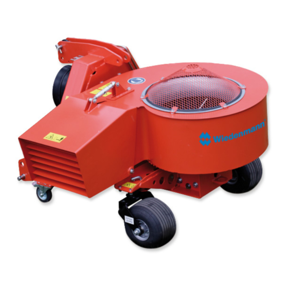
- Page 1 Translation of original Operating Instructions Leaf blower Mega Twister 894.000 From equipment I.D. No. : Status : June 2014 894 99 01...
- Page 2 All information, illustrations and specifications in these Operating Instructions are based on the latest information available at the time of publication. We reserve the right to make design changes at any time without prior notification...
- Page 3 All information, illustrations and specifications in these Operating Instructions are based on the latest information available at the time of publication. We reserve the right to make design changes at any time without prior notification...
- Page 4 Preface READ THESE OPERATING INSTRUCTIONS CAREFULLY to familiarise yourself with the correct way to operate and service your machine, and to prevent personal injury or damage to the machine. These operating instructions and the adhesive safety signs on your machine can also be obtained in other languages (your dealer can order these for you).
-
Page 5: Table Of Contents
Mounting the lower guide bar extension..24 2.9. Mounting the upper guide bar extension..24 3.0. Transport..........25-28 3.1. General information......25 3.2. Transporting Mega Twister...... 26+27 3.3. Transportation with three-point hitch..28 4.0. Mounting..........29-32 4.1. General information......29 4.2. - Page 6 TABLE OF CO N T E N T S Page * * * * * * * * * * * * * * * * * * * * * * * * * * * * * * * * * * * * * * * * * * * * * * * * * * * 8.0.
-
Page 7: Safety
1.0. Safety Recognize safety information This is the safety-alert symbol. When you see this symbol on your machine or in this manual, be alert to the potential for personal injury. Follow recommended precautions and safe operating practices. Follow safety instuctions Carefully read all safety messages in this manual and on your machine safety sings. - Page 8 1.0. Safety Observe road traffic regulations Always observe local road traffic regulations when using public roads. SCHUTZKLEIDUNG TRAGEN Wear close fitting clothing and safety equipment appropriate to the job. Prolonged exposure to loud noise can cause impairment or loss of hearing. Wear a suitable hearing protective device such as earmuffs or earplugs to protect...
- Page 9 1.0. Safety Guard and shields Keep guards and shields in place all the times. Ensure that they are in good condition and installed correctly. Always disengage the driveline, shut off engine and remove key before removing any guards or shields. Keep hands, feet and clothing away from moving parts.
- Page 10 1.0. Safety Use safety lights and devices Prevent collisions between other road users, slow moving tractors with attachments or towed equipment, and self- propelled machines on public roads. Frequently check for traffic from the rear, especially in turns, and use hand signals or turn signal lights.
- Page 11 1.0. Safety Remove paint before welding or heating Welding should only be carried out by persons with a relevant qualifying certificate i.a.w. EN287. Avoid potentially toxic fumes and dust. Hazardous fumes can be generated when paint is heated by welding, soldering, or using a torch.
-
Page 12: Safety Decals
1.0. Safety 1.1. Safety Decals Pictorial safety signs At several important places, this machine has safety signs, which indicate potential danger. The hazard is identified by a symbol in a warning triangle. An adjacent pictograph provides information on how to avoid personal injury. - Page 13 1.0. Safety 1.1. Safety Decals Blower Never put your hands inside the blower while the engine is running. 894.03 Blow-out cover When operating ensure that sufficient distance is left as there is a risk of injury from thrown or flying objects. 894.04 Direction of rotation and number of revolutions of the power take-off shaft...
- Page 14 1.0. Safety 1.1. Safety Decals Service Before performing service or repair work, turn off engine and remove key. 894.06 Noise level This decal indicates the value determined in accordance with Article 13 of Directive 2000/14/EC 894.07 When working for several hours, we recommend that you wear ear protectors.
-
Page 15: Safety Instructions
.0. Safety 1.2. Safety instructions 1. When observing the 9. Any mounting on the operating instructions mounted implement must be also pay attention to done only when the motor general safety is stopped and the power specifications and rules take-off shaft is turned for the prevention of off. -
Page 16: The Safety Devices
Do not operate the machine when children and others are around. d) Do not allow operation of the machine by untrained personnel. ATTENTION - DANGER ! Never use Mega Twister without safety equipment. Otherwise, you expose yourself and others to extreme danger. Moving parts may cause serious injuries. -
Page 17: Assembly
2.0. Assembly 2.1. General Information WARNING: For all work, the device must For this work, please use your be hitched to the tractor. personal protective equipment Raise the attached device (PSA) such as: gloves, using the rear hydraulics goggles, ear protectors. until the support legs can be inserted into one of the uppermost holes. -
Page 18: Assembling The Roller Unit
2.0. Assembly 2.3. Assembling the roller unit The attachment points for the roller unit are: 4 threaded holes (A) 2 holes (B) Fix the bracket (C) on both sides. The hexagon screws (D) must be inserted from below. Use the bearings to fix both ends of the roller (E), with two hexagon screws (F) in each case, in the front holes of the bracket... -
Page 19: Hydraulically Adjusting The Blow-Out Nozzle
2.0. Assembly 2.4. Hydraulically adjusting the blow-out nozzle Carried out via an additional hydraulic cylinder (optional) Mount the hydraulic cylinder instead of the mechanical adjustment. Secure pin with linch pin. Screw the hexagon screw (A) into the thread on the grille (B). - Page 20 2.0. Assembly 2.5. Hydraulically adjusting the blow- out nozzle using a control valve Remove the hydraulic hoses (A) from the Mega Twister on the tractor. Secure the control valve and its fixing bracket to the available hexagon screws (B) on the front.
- Page 21 2.0. Assembly 2.5. Hydraulically adjusting the blow- out nozzle using a control valve Connect the hydraulic hose (G) from the control valve to the hydraulic cylinder's threaded connection (H). Connect the hydraulic hose (J) 90 from the control valve to the hydraulic cylinder's threaded connection (K).
- Page 22 2.0. Assembly 2.6. Electric adjustment of the blow-out nozzle Screw the ring bolt (A) into the thread on the grille (B). Turn the hexagon nut (C) downwards to secure the ring bolt in place. Attach the electrospindle (D) to the mechanical adjustment. Fit the bracket (E) to the electrospindle.
-
Page 23: Attaching The Blowout Nozzle
2.0. Assembly 2.7. Attaching the blow-out nozzle Hook the blow-out nozzle (A) on with the slot on the locking pin (B) Push the shaft (C) from the left into the bearing bushing. NOTE: On the left-hand side insert 1 spacer ring and on the right-hand side insert 2 spacer rings between the housing and the blow-out... -
Page 24: Mounting The Lower Guide Bar Extension
2.0. Assembly 2.8. Mounting the lower guide bar extension Remove lower guide bar bolt. Insert lower guide bar extension (A) with bolt (B) from the inside to the outside. Secure using the lock washer and hexagon nut. 2.9. Mounting the upper guide bar extension Remove upper guide bar bolt. -
Page 25: Transport
Never stand under lifted loads. There is an imminent danger to life if the load falls. Improper transport and mounting of Mega Twister can result in: injury to persons damage to property. Pay special attention to the direction of approach when lifting the machine with the transport frame. - Page 26 Risk of injury due to ends “springing open”. 3.2.1. Transport Using a Forklift If the Mega Twister is still secured to the transport frame: insert the forks under the transport frame (pay attention to the direction of approach), ...
- Page 27 3.0. Transport 3.2. Transporting Mega Twister 3.2.3. Mounting point for transport on a trailer CAUTION DANGER Please note the removal instructions in Chapter 5.2. - DANGER OF TOPPLING ! Tighten tie-down straps evenly, alternating diagonally across. Hooking points for straps...
-
Page 28: Transporting Mega Twister
When driving on public roads, please observe the swivel range of the attached Mega Twister. All information, illustrations and specifications in these Operating Instructions are based on the latest information available at the time of publication. We reserve the right to make design changes at any time without prior notification... -
Page 29: Mounting
4.0. Mounting 4.1. General Information WARNING: Mount the machine only with Check the engine speed and the engine shut off and the sense of rotation (stickers on PTO switched off. The the machine) against the signboards applied on the specifications of your machine show important tractor. -
Page 30: Drive Shaft Adjustment
4.0. Mounting 4.3. Drive shaft adjustment To adjust the length, hold the half shafts next to each other in the shortest working position and mark them. Shorten inner and outer protective tubes equally. Shorten inner and outer sliding profiles by the same length as the protective tubes. -
Page 31: Supports
4.0. Mounting 4.4. Supports Insert the two legs in the uppermost position and secure them with the spring clip. 4.5. Unscrewing the running gear safety device Pull the locating pin (B) upwards out of the wheel yoke hole. For locking, pivot the locating pin (B) to the right in the raised position. -
Page 32: Hydraulic Connections
4.0. Mounting 4.6. Hydraulic connections For hydraulic swiveling of the blow-out nozzle an independently switchable, double-acting hydraulic valve is necessary. The hydraulic hoses of the swivel mechanism are equipped with connectors of size 3. Before coupling, the connectors and sockets have to be cleaned thoroughly in order to prevent impurities from getting into the hydraulic circuit. -
Page 33: Demounting
Mega Twister. Release bottom connecting rod Attach pin to Mega Twister and secure with linch pin. All information, illustrations and specifications in these Operating Instructions are based on the latest information available at the time of publication. -
Page 34: Stowing The Hydraulic Lines
5.0. Demounting 5.3. Stowing the hydraulic lines Hook the hydraulic lines into the holder (A). 5.4. Removing the universal drive shaft Pull the bracket (A) upwards and pivot it forwards by approx. 45° to the nearest engaging point. ... -
Page 35: Operating
6.0. Operating 6.1. General Information CAUTION DANGER! Protective covering (A) must be replaced by the blowout nozzle included in the delivery before the initial start-up (see section 2.7.). ATTENTION ! It is important to become familiar with all devices and operating elements as well as their action before starting service to make sure that all protective devices... -
Page 36: Direction Of Rotation Number Of Revolutions Of The Drive
6.0. Operating 6.2. Direction of rotation and number of revolutions of the drive The machine is designed for a maximum speed of the power take- off shaft of 750 rpm. ATTENTION! We strongly advise you against using another speed of the power take-off shaft other than 750 rpm Exceeding the speed of the power... -
Page 37: Swiveling The Blower Casing
6.0. Operating 6.4. Swiveling the blower casing using the hydraulic motor By activating the double-acting hydraulic valve the blower casing with blow-out funnel is swiveled from the left to the right side and back again. Depending on the hydraulic capacity of the tractor, swiveling the blower casing is started by a careful activation of the control valve. -
Page 38: Operation
Direct everyone out of the danger zone before starting. always switch off before Switch off the drives you lift up the Mega Twister immediately if there are people in the danger zone. 7.2. Switching on The blower may not be... -
Page 39: Danger Zone
7.0. Operation 7.4. Danger zone CAUTION! Switch off the drives immediately if there are people in the danger zone. During operation, you must ensure there is sufficient free space for any flying debris: Clearance "R" approx 50 m In order to avoid injury to persons or damage to equipment. -
Page 40: Maintenance
8.0. Maintenance 8.1. General Information ATTENTION! parts from Wiedenmann. For all work, the device We expressly point out to must be hitched to the you that non-original tractor. parts that have not been - RISK OF INJURY ! delivered by Wiedenmann... -
Page 41: Intervals Of Maitenance
8.0. Maintenance 8.2. Intervals of maintenance Maintenance Area Maintenance measure interval Blower CLEAN Clean the machine after finishing work in order to ensure a proper Daily operation during the next application. Hydraulic Rotating assembly system Maintenance Area Maintenance measure interval Cardan shaft LUBRICATE –... -
Page 42: Lubricating Points
8.0. Maintenance 8.3. Lubricating points 8.3.1. Cardan shaft Grease inside the exterior sliding profile. Before a longer stop periood clean and lubricate the drive shaf. In case of dirt accumulation clean the profile and protection pipes. All information, illustrations and specifications in these Operating Instructions are based on the latest information available at the time of publication. - Page 43 8.0. Maintenance 8.3. Lubricating points ATTENTION For this work, raise the attached device using the rear hydraulics until the support legs can be inserted into one of the uppermost holes. 8.3.2. Rotating assembly There are two grease nipples on the rotating assembly positioned opposite to each other.
-
Page 44: Changing The Gear Oil
8.0. Maintenance 8.4. Changing the gear oil ATTENTION: Leaking fluids can penetrate the skin and cause serious injury. Place a collecting tray underneath the gearbox. Remove the drain screw (A) Remove the exhaust filter(E). Catch the oil draining out in a suitable vessel. -
Page 45: Cleaning
8.0. Maintenance 8.5. Cleaning The main point to be cleaned is the air intake grid. When using compressed air or high-pressure cleaners be careful that no water, dirt or other impurities can penetrate the gear or the bearing. 8.6. Hydraulic installation ATTENTION! Leaking fluid under pressure can penetrate the skin... -
Page 46: Hydraulic Connection Diagram
8.0. Maintenance 8.7. Hydraulic connection diagram 8.7.1. Pivoting the blower housing 894.19 Hydraulically adjusting the blow-out nozzle 8.7.2. 894.32 All information, illustrations and specifications in these Operating Instructions are based on the latest information available at the time of publication. We reserve the right to make design changes at any time without prior notification... - Page 47 8.0. Maintenance 8.7. Hydraulic connection diagram 8.7.3. Hydraulically adjusting the blow-out nozzle using a control block 894.33 All information, illustrations and specifications in these Operating Instructions are based on the latest information available at the time of publication. We reserve the right to make design changes at any time without prior notification...
- Page 48 8.0. Maintenance 8.8. Tire pressure The tire pressure depends on the soil conditions. Paved ways and areas, good bearing turf or soil Tire pressure maximum 2,0 bar. The tire pressure depends on the soil conditions. Tire pressure minimum 0,5 –...
-
Page 49: Disassembly / Disposal
heavy parts that could fall after disassembly, sharp edges, crushing if machine topples. Disassembly for disposal 1. Place Mega Twister on firm ground. 2. Drain hydraulic oil. 3. Disassemble Mega Twister, working from top to bottom. IMPORTANT:... -
Page 50: Unauthorized Conversion And Spare Part Manufacture
The use of other parts can change the properties of the Mega Twister. In this case, the manufacturer is exonerated from liability in the event of damage. All information, illustrations and specifications in these Operating Instructions are based on the latest information available at the time of... -
Page 51: Equipment
9.0. Equipment 9.1. Scope of Delivery Leaf blower Mega Twister model no. 894 front mounted in 3-point linkage cat. I for front PTO stub shaft with anticlockwise rotation leaf blower Mega Twister model no. 895 front mounted in 3-point linkage cat. -
Page 52: Special Equioment
9.0. Equipment 9.2. Special equipment hydraulic adjustment of the blow-out nozzle Hydraulic control block for tractors with only two hydraulic connections. Electric adjustment of the blow- out nozzle Blow-out nozzle close to the ground All information, illustrations and specifications in these Operating Instructions are based on the latest information available at the time of publication. - Page 53 9.0. Equipment 9.2. Special equipment Lower guide bar extension 200 mm Lower guide bar extension 150 mm Upper guide bar extension 200 mm Upper guide bar extension 150 mm All information, illustrations and specifications in these Operating Instructions are based on the latest information available at the time of publication.
-
Page 54: Specification
Max. allowed speed of the blowing wheel 840 rpm Blowing performance 390 m³/min Blowing speed 50 m/s Weights : Mega Twister Neutral 266 kg Complete chassis 38 kg Hydraulics for adjusting the blow-out nozzle 3 kg Hydraulics for adjusting the blow-out nozzle using a control valve... - Page 55 9.0. Specification 10.1.1. Dimensions, weights and other information - with chassis 894.38 All information, illustrations and specifications in these Operating Instructions are based on the latest information available at the time of publication. We reserve the right to make design changes at any time without prior notification...
- Page 56 840 rpm Blowing performance 390 m³/min Blowing speed 50 m/s Weights : Mega Twister Neutral 266 kg Complete roller unit 26 kg Hydraulics for adjusting the blow-out nozzle 3 kg Hydraulics for adjusting the blow-out nozzle using a control valve...
- Page 57 10.0. Specification 10.1.2. Dimensions, weights and other information - with roller unit F1 F2 E1 E2 894.39 All information, illustrations and specifications in these Operating Instructions are based on the latest information available at the time of publication. We reserve the right to make design changes at any time without prior notification...
-
Page 58: Metric Bolt And Cap Screw Torque Values
10.0. Specification 10.2. Metric bolt and cap screw torque values Property Class and Head Markings Property Class and Markings class 4.8 class 8.8 or 9.8 class 10.9 class 12.9 Lubricated * Dry ** Lubricated * Dry ** Lubricated * Dry ** Lubricated * Dry ** Größe... -
Page 59: Serial Number
Wiedenmann D-89192 Rammingen Mega Twister 894.40 _ _ _ _ _ _ _ _ _ _ _ _ _ _ _ _ _ Prod. Ident. No. : All information, illustrations and specifications in these Operating Instructions are based on the latest information available at the time of...
Need help?
Do you have a question about the Mega Twister and is the answer not in the manual?
Questions and answers