Table of Contents
Advertisement
Quick Links
OPERATING INSTRUCTION MANUAL
FOR THE
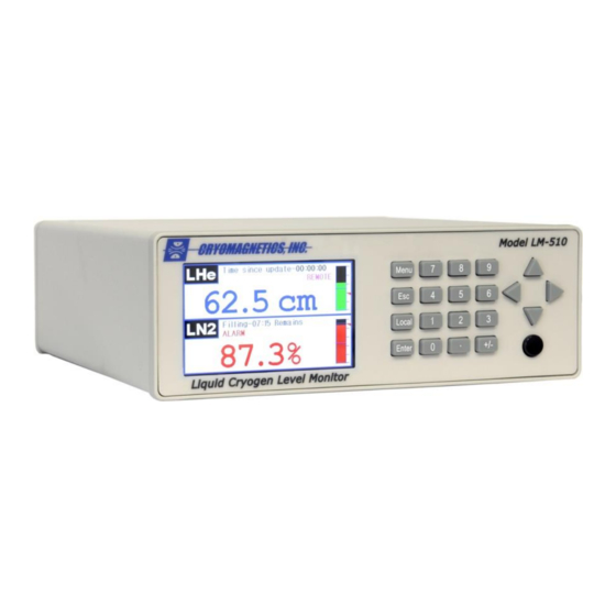
MODEL LM-510
LIQUID CRYOGEN
LEVEL MONITOR
1006 Alvin Weinberg Drive
Oak Ridge, Tennessee 37830
Phone: (865) 482-9551
Fax: (865) 483-1253
Web: http://www.cryomagnetics.com
WARNING!
DO NOT ATTEMPT TO OPERATE THIS EQUIPMENT BEFORE YOU
HAVE THOROUGHLY READ THIS INSTRUCTION MANUAL.
LM-510 Operating Instruction Manual – Revision 1.3
Advertisement
Table of Contents

Related Manuals for CRYOMAGNETICS LM-510

Summary of Contents for CRYOMAGNETICS LM-510
- Page 1 LEVEL MONITOR 1006 Alvin Weinberg Drive Oak Ridge, Tennessee 37830 Phone: (865) 482-9551 Fax: (865) 483-1253 Web: http://www.cryomagnetics.com WARNING! DO NOT ATTEMPT TO OPERATE THIS EQUIPMENT BEFORE YOU HAVE THOROUGHLY READ THIS INSTRUCTION MANUAL. LM-510 Operating Instruction Manual – Revision 1.3...
- Page 3 MANUFACTURER'S DECLARATION OF CONFORMITY According to lSO / IEC Guide 22 and EN45014 Manufacturer's Name: Cryomagnetics, Inc. Manufacturer's Address: 1006 Alvin Weinberg Drive Oak Ridge, TN 37830 Declares. the product Product Name: Liquid Cryogen Level Monitor Model Number: LM-510 Product Options:...
-
Page 5: Table Of Contents
Appendix A - Computer Interface Command Reference ..........33 Appendix B - Line Voltage Controller Module – Option 4 ..........52 Appendix C - Factory Calibration / Firmware Updates ............ 53 Liquid Helium Channels......................53 LM-510 Operating Instruction Manual – Revision 1.3... - Page 6 Appendix E - Helium Recondenser Controller Option ............. 55 List of Figures - Figure 1 - LM-510 / Dual Channel LHe-LN2 ..................1 Figure 2 - LM-510 Rear Panel ......................7 Figure 3 - LHe Level Sensor Connector Wiring .................. 7 Figure 4 - LN2 Level Sensor Connector Wiring ..................
-
Page 7: Introduction
LM-510 can monitor many manufacturers’ capacitive sensors due to advanced circuit design. The LM-510 has user-adjustable high and low set points that may be used to control automated refill cycles. With the two-channel option, independent set points can be adjusted for each channel. - Page 8 This insures reliable, accurate level readings even under the most adverse cryogenic conditions. Computer control of the LM-510 is possible via USB and Ethernet interfaces – both are provided in the standard configuration. IEEE-488 and RS-232 interfaces are available as options. LabVIEW®...
- Page 9 LM-510-xx-4 Line Voltage Controller Output The LM-510 is designed to operate per the specifications in this table and the instructions provided in this manual. Other use may impair the safety protections provided by the equipment. LM-510 Operating Instruction Manual – Revision 1.3...
- Page 10 This Page Intentionally Left Blank LM-510 Operating Instruction Manual – Revision 1.3...
-
Page 11: Factory Calibrations, Installed Options And Certification
Lead Resistance: Input Channel 2: Not Installed: Type: Other: Calibration: Sensor Manufacturer / Serial No: Sensor Length: Characteristic Resistance/Voltage: Lead Resistance: Computer Interface Installed: IEEE-488.2 (Option 1) : RS-232(Option 2): Notes: Certified: Date: LM-510 Operating Instruction Manual – Revision 1.3... - Page 12 This Page Intentionally Left Blank LM-510 Operating Instruction Manual – Revision 1.3...
-
Page 13: Instrument Setup And Sensor Connection
Figure 2 - LM-510 Rear Panel Line Voltage and Fuse The LM-510 is designed to operate with any AC power source between 100V and 240V A.C. and 50 to 60 Hz. No user serviceable fuse is provided. Connecting Sensors, Relay functions, and Analog Outputs Sensors connect to the LM-510 at the rear panel using circular connectors located above the labels ‘Channel 1’... -
Page 14: Figure 4 - Ln2 Level Sensor Connector Wiring
Connections should be double- checked for accuracy prior to attaching to the LM-510 and powering the unit ON since liquid helium level sensors are driven by high voltages (up to 70 volts DC). These high voltages could damage liquid nitrogen sensors or other sensors (such as temperature sensors or hall probes) should these be accidentally connected. -
Page 15: Figure 5 - Auxiliary Connector Wiring - Db-9F
2 lead wires, the I- and V- leads are combined into a single black lead and the V+ lead is not used. The V+ connection at the input to the LM-510 should be connected to the I+ terminal in this case. - Page 16 This Page Intentionally Left Blank LM-510 Operating Instruction Manual – Revision 1.3...
-
Page 17: Operation And Menus
If your LM-510 is configured for dual sensor inputs, the top half of the display will indicate Sensor #1 and the bottom half will indicate Sensor #2. If your LM-510 is configured for a single sensor input, the display will only indicate one level. -
Page 18: Menu Organization
If the LM-510 is operating in sample/hold mode with a liquid helium level sensor, the top line of the display will show a timer that indicates how long ago the displayed reading was taken. The interval between readings may be adjusted (see section 4.2.1 below). -
Page 19: Figure 7 - Lm-510 Menu Hierarchy
•Off •Off MAC Address Timeout Timeout Socket Units Units •Centimeters •Centimeters Audio Alarm •Inches •Inches •Percent •Percent Boost Sensor Length •Off •On Zero Offset •Smart Sensor Length Gain Lead Resistance Ohms per CM LM-510 Operating Instruction Manual – Revision 1.3... -
Page 20: Liquid Helium Level Channel
Liquid Helium Level Channel To set up a liquid helium level sensor, power ON the LM-510 and press the MENU key. Use the ◄► keys to select the appropriate sensor channel tab at the top of the display, then the ▲▼ keys to select the sensor parameter to be calibrated. -
Page 21: Control Mode
The set points for the high and low alarms (entered in %) are set in the “Alarm Lo” and “Alarm Hi” fields in the LM-510 Menu. Separate set points are available for each channel if the two channel option is installed. -
Page 22: Sensor Active Length
ESC to exit without saving the changes. Liquid Nitrogen (Capacitive) Level Channel To set up an LN2 sensor, power ON the LM-510 and press the Menu key. Use the ◄► keys to LM-510 Operating Instruction Manual – Revision 1.3... -
Page 23: Alarm Set Points
Alarm Set Points The LM-510 has alarm set points that may be used to alert the operator when the LN2 level falls below a user-settable threshold or exceeds a high alarm level. The set points for the high and low alarms (entered in %) are set in the “Alarm Lo”... -
Page 24: Units
4.3.3 Units The Units menu item allows the user to set the display units of the LM-510 for this particular channel. Available options are percent (%), centimeters (cm), or inches (in). Note that sensor lengths (see Sect. 4.2.5 below) must be entered in centimeters. -
Page 25: Setup Menu
The LM-510 has numerous general setup parameters that may be configured in the Setup tab. Figure 10 - Setup Menu The user may select which type of interface is used for communication with the LM-510. USB and LAN (Ethernet) interfaces are standard with all instruments. -
Page 26: Advanced Menu - Firmware Updates And Ln2 Sensor Configuration
Advanced Menu – Firmware Updates and LN2 Sensor Configuration The LM-510 has a hidden menus for updating the front panel and channel card firmware and also is used for configuring LN2 sensors. The menu is accessed by entering the last seven digits of the main Cryomagnetics phone number (4829551) and pressing the <Menu>... -
Page 27: Firmware Update
4.5.2 Firmware Update The LM-510 has several processors. The Ethernet module is the starting point for loading new instrument firmware. The version identifiers of the installed firmware and version numbers of firmware loaded into the Ethernet module are shown on this display. The user will be prompted to install firmware updates when different firmware is loaded and this display is accessed. - Page 28 This Page Intentionally Left Blank LM-510 Operating Instruction Manual – Revision 1.3...
-
Page 29: Control Interfacing
The LM-510 ”Ctrl Mode” may be set to Auto, Manual or Off. A fill cycle may be initiated manually by selecting ‘Manual’ for the control mode setting. When the manual fill cycle completes the Ctrl Mode will transition to ‘Off’. -
Page 30: Figure 13 - Typical Automatic Cryogen Refill System
Figure 13 - Typical Automatic Cryogen Refill System If your LM-510 has the two channel option installed, two totally independent cryogenic systems can be under automatic refill control by a single LM-510. LM-510 Operating Instruction Manual – Revision 1.3... - Page 31 The control output(s) of the LM-510 may be disabled by setting the control mode to Off. • The Timeout setting of the LM-510 should be set to a value which the user is confident is beyond the time needed for a worst-case cryogen transfer, but no further. Should the...
-
Page 32: Using Ctrl As An Alarm
100% the high level control is disabled. Doing either of these effectively will give the user the ability to set another alert or alarm level in the LM-510 with an associated relay contact. For instance, by setting the Ctrl High to 100% (disabling it) and the Ctrl Low to 20%, the user will be alerted on the display when the liquid cryogen level drops to 20%. -
Page 33: Theory Of Operation
Liquid Helium Level Sensing (Superconductive Filament Probes) If at least one input of the LM-510 is configured for liquid helium level sensors, the unit may be used with 2, 3 or 4 wire superconductive filament level sensors for monitoring liquid helium (an industry standard). -
Page 34: Liquid Nitrogen Level Sensing (Capacitive Probes)
The LM-510 can easily subtract out all of these errors to give a stable, accurate reading of liquid helium level. The LM-510 contains circuitry allowing it to sample a liquid helium level sensor at a predetermined interval or on demand. -
Page 35: Lm-510 Circuit Description
Also included is an Ethernet interface module that enables firmware updates for all the onboard processors to be easily and reliably installed in the field. The LM-510’s display is a bright 240x400 TFT LCD unit having high contrast and a wide viewing angle. - Page 36 This Page Intentionally Left Blank LM-510 Operating Instruction Manual – Revision 1.3...
-
Page 37: Limited Warranty Policy
This warranty shall be effective for one (1) year after the date of shipment from Cryomagnetics. Cryomagnetics reserves the right to elect to repair, replace, or give credit for the purchase price of any product subject to warranty adjustment. Return of all products for warranty adjustment shall be FOB Oak Ridge, TN, and must have prior authorization for such return from an authorized Cryomagnetics, Inc. - Page 38 This Page Intentionally Left Blank LM-510 Operating Instruction Manual – Revision 1.3...
-
Page 39: Appendix A - Computer Interface Command Reference
Appendix A - Computer Interface Command Reference Front panel functions of the LM-510 may be accessed using command strings over the selected computer interface. The following sections detail available commands and requird syntax. The commands available through USB and LAN (Ethernet) are identical to those available through IEEE-488.2;... - Page 40 0 - 31. Factory default is 0. HTTP Interface An HTTP interface is provided for the LM-510 to allow simple remote monitoring of sensor readings and allows a new reading to be initiated if a liquid helium channel is being monitored. To use this capability the login “lm510”...
- Page 41 Liquid Helium Level Sensor are addressed to a Liquid Nitrogen channel, a device dependent error is reported in the ESR, and message "Parameter error" will be returned if error reporting is enabled when using the RS-232 interface. LM-510 Operating Instruction Manual – Revision 1.3...
- Page 42 The following table lists the LM-510 commands, shows the LM-510 mode and channel where the command may be used, and provides a short command description. Command details are provided in the reference that follows. Command Available Description BOOST LHe Operate...
- Page 43 Wait-to Continue Command Command Reference This section describes how each LM-510 command is used and provides a cross-reference to related commands. The command syntax sections show required elements enclosed in <angle brackets> and optional parameters enclosed in [square brackets]. All numbers are decimal (base 10).
- Page 44 Availability: LN2 Channel in Operate Mode Command Syntax: CAPLO <Value> Example: CAPLO 155.3 Parameter Range: [0.1 : 2000] Description: The CAPLO command sets the empty capacitance level for an LN2 probe. This is LM-510 Operating Instruction Manual – Revision 1.3...
- Page 45 1 when power is applied or when the *RST command is sent. Related Commands: BOOST, BOOST?, CHAN?, FILL, FILL?, H-ALM, H-ALM?, HIGH, HIGH?, INTVL, INTVL?, L-ALM, L-ALM?, LNGTH?, LOW, LOW?, MODE, MODE?, MEAS, MEAS?, TYPE?, UNITS, UNITS?, *RST LM-510 Operating Instruction Manual – Revision 1.3...
- Page 46 Timeout time was exceeded, and that Control Relay is inhibited until the operator resets the Ctrl Timeout by selecting MENU on the LM-510 or issuing a *RST command via the computer interface. The Timeout can be inhibited by setting the value to zero in the Ctrl Menu for the channel.
- Page 47 LM-510. The last ERROR setting will be retained even when the instrument is off. It will power up as configured by the last ERROR command.
- Page 48 Response Range: 00:00:00 to 99:59:59 Description: The INTVL? query returns the time between samples for the selected Liquid Helium Level Meter channel. Time is in hours, minutes, and seconds. Related Commands: CHAN, CHAN?, INTVL LM-510 Operating Instruction Manual – Revision 1.3...
- Page 49 Availability: Always (RS-232 Only) Command Syntax: LOCAL Description: The LOCAL command returns control the front panel keypad after remote control has been selected by the REMOTE or RWLOCK commands. Related Commands: REMOTE, RWLOCK LM-510 Operating Instruction Manual – Revision 1.3...
- Page 50 READY bit for the selected channel will be set in the status byte returned by the *STB? command when the measurement is complete. Related Commands: CHAN, CHAN?, MEAS?, *STB? MEAS? Query last completed measurement on selected channel Availability: Operate Mode Command Syntax: MEAS? [Channel #] LM-510 Operating Instruction Manual – Revision 1.3...
- Page 51 The sample mode may have been set by a MODE command or the front panel menu. Related Commands: CHAN, CHAN?, INTVL, INTVL?, MODE OSC? Query LN2 to see if old style oscillator is connected Availability: LN2 in Operate Mode LM-510 Operating Instruction Manual – Revision 1.3...
- Page 52 Command Syntax: REMOTE Description: The REMOTE command takes control of the LM-510 via the remote interface. All buttons on the front panel are disabled except the Local button. This command will be rejected if the menu system is being accessed via the front panel or if LOCAL has been selected via the Local button on the front panel.
- Page 53 Description: The UNITS command sets the units to be used for all input and display operations for the default channel selected by a prior CHAN command. Units may be set to centimeters, inches, or percentage of sensor length. Related Commands: H-ALM, H-ALM?, CHAN, CHAN?, HIGH, HIGH?, L-ALM, L-ALM?, LM-510 Operating Instruction Manual – Revision 1.3...
- Page 54 Standard Event Status Enable Query Availability: Always Command Syntax: *ESE? Response: <ESE Mask> Response Example: Response Range: 0 to 255 Description: The *ESE? command operates per IEEE Std 488.2-1992 by returning the mask set in LM-510 Operating Instruction Manual – Revision 1.3...
- Page 55 Response Example: Cryomagnetics,LM-510,2002,2.00 Serial # Range: 2000 to 9999 Firmware Level Range: 1.00 to 9.99 Description: The *IDN? command operates per IEEE Std 488.2-1992 by returning the LM-510 manufacturer, model, serial number and firmware level. Related Commands: None *OPC Operation Complete Command...
- Page 56 Availability: Always Command Syntax: *OPC? Description: The *OPC command operates per IEEE Std 488.2-1992 by placing an ASCII character "1" in the output queue since the LM-510 does not defer any commands for later processing. Related Commands: *OPC *RST Reset Command...
- Page 57 Always Command Syntax: *WAI Description: The *WAI? command operates per IEEE Std 488.2-1992 by accepting the command without generating an error. Since the LM-510 only implements sequential commands the no- operation-pending flag is always TRUE. Related Commands: OPC, *OPC? LM-510 Operating Instruction Manual – Revision 1.3...
-
Page 58: Appendix B - Line Voltage Controller Module - Option 4
Appendix B - Overview The Line Voltage Controller Module enables the LM-510 to control one or two 115/230 VAC loads up to 1 Amp each using the LM-510 Low and High setpoints. Section 5.5, Automatic Refill, describes operation of the LM-510 in automatic refill applications. The outputs are labeled channel 1 and channel 2, and are controlled by the respective channels of the LM-510. -
Page 59: Appendix C - Factory Calibration / Firmware Updates
200 cm long, and are excited with a constant current of 70 mA. This means voltages at the output of the LM-510 may be as high as ~70V DC. The power capacity of the calibration resistor must also be considered. -
Page 60: Appendix D - Updated Ln2 Probe Notes
See the below instructions for calibration instructions. 1. Calibrate empty level 1.1. Attach the probe to an LM-510 and a warm, dry LN2 sensor. Power on the LM-510. 1.2. Go to the LN2 channel’s menu and set Units to picoFarads, then press Menu to return to the top display. -
Page 61: Appendix E - Helium Recondenser Controller Option
Appendix E - Helium Recondenser Controller Option The LM-510 can be configured with a Helium Recondenser Controller installed in Channel 2. It is designed to monitor pressure in a cryostat containing liquid helium and helium vapor that is equipped with helium reliquifier, and to add heat to the system as needed to maintain an optimal pressure for recondensing. - Page 62 The maximum heater power is set in the menu, and the bar to the right of the pressure LM-510 Operating Instruction Manual – Revision 1.3...
- Page 63 Figure E-3 HRC Menu E.3.1.1 Setpoint The pressure setpoint is the target pressure used to control heater output. A PID algorithm is used to adjust heater output when the heater is enabled. LM-510 Operating Instruction Manual – Revision 1.3...
- Page 64 The system is designed to use linear pressure sensors, so calibration involves setting of a zero pressure baseline (Offset) and a known pressure (Gain). Calibration of the HRC is performed as follows: LM-510 Operating Instruction Manual – Revision 1.3...
- Page 65 Accuracy does not suffer significantly since calibrated 12-bit resolution is provided for each 4-20mA output. Figure E-4 HRC Analog Outputs 1 – Pressure Out 2 – Pressure Rtn 5 – Shield 4 – Heater Rtn 4 – Heater Out LM-510 Operating Instruction Manual – Revision 1.3...
- Page 66 Enable/Disable HRC heater Availability: HRC Operate Mode Command Syntax: HEAT <ON, OFF> Example: HEAT ON Default Parameter: None Parameter Range: ON, OFF Description: The HEAT command enables or disables the HRC heater. Related Commands: HEAT? LM-510 Operating Instruction Manual – Revision 1.3...
- Page 67 MEAS? [Channel #] Example: MEAS? 2 Default Parameter: Default Channel (See CHAN) Parameter Range: 1 to 2 Response: <Pressure> <Units> <Heater Power> W Response Example: 3.125 psi 2.487 W (example for HRC channel) LM-510 Operating Instruction Manual – Revision 1.3...
- Page 68 Query target operating pressure Availability: Operate Mode Command Syntax: PSET? Response: <Target Operating Pressure> <Units> Response Example: 2.500 psi Description: The PSET? query returns the target operating pressure in the present units. Related Commands: PSET LM-510 Operating Instruction Manual – Revision 1.3...
Need help?
Do you have a question about the LM-510 and is the answer not in the manual?
Questions and answers