Table of Contents

Related Manuals for DESSALATOR DUO D100


Summary of Contents for DESSALATOR DUO D100
- Page 1 DUO D100 (AC/DC) 100 liters/hour – 12 (or 24V) and 230 (or 120V) ASSEMBLY AND USER MANUAL Dessalator® ZI des 3 Moulins 282 rue des Cistes 06600 Antibes, France www.dessalator.com contact@dessalator.com DUO-100 v2.4 (04/2021)
-
Page 2: Table Of Contents
High-pressure pump ....................21 Spare Parts ..........................22 Appendix A1: How do watermakers work? ................23 Appendix A2: Mounting of the DESSALATOR® high-pressure nozzles ....... 24 Appendix A3: Manual Rinsing Procedure ................25 Appendix A4: Instructions for the Sterilizing Cartridge ............26 Appendix A5: Troubleshooting .................... -
Page 3: Copyright / Disclaimer
Copyright / Disclaimer Dessalator® ZI des 3 Moulins, 282 rue des Cistes Bâtiment Euro 92 06600 Antibes, France www.dessalator.com contact@dessalator.com +33 4 93 95 04 55 DUO-100 v2.4 (04/2021) Page 3... -
Page 4: List Of Components
List of Components Hull Valve Ø Must be placed as low as possible in the boat so as to avoid drawing in any air Ø Must be installed towards the back for a motorboat, or centered near the keel for a sailboat. The ribs of the strainer should be placed towards the front the boat to force the entry of water by scooping during navigation. - Page 5 Motor/Pump Block Ø Must ideally be placed beneath the waterline for optimal yield/output. ➥Note: If it is not possible to install the motor block beneath the waterline, it is necessary to install the optional booster pump. Ø Composed of the 12 or 24 Volt motor and the 120 or 230 Volt motor. Ø...
-
Page 6: Assembly
Ø 4 special DESSALATOR® fittings* for high-pressure piping (see assembly procedure in Appendix A2). § * Including one 90° elbow fitting for the back of the control panel, which can swivel 360°. -
Page 7: Seawater Inlet
2) Seawater inlet Seawater inlet valve Ø The strainer should be placed as low as possible beneath the waterline so that it does not draw in any air. It should be placed far from the discards. Ø Pierce the hull with a Ø 21mm hole saw. Ø... - Page 8 Ø The connection for fresh water rinsing must be done with water from the pressurized freshwater system. Ø A solenoid valve is mounted behind the prefilter for automatic rinsing. Ø The valve handle must be in seawater position (see diagram above with the 3 positions of the 3-way valve).
-
Page 9: Motor/Pump Block
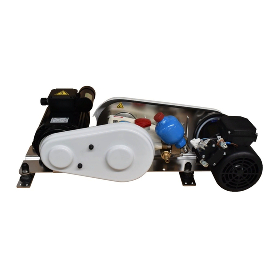
3) Motor/Pump Block Ø To ensure optimal production, the assembly of the high-pressure motor block must be completed as low as possible in the boat, in a horizontal position and in an area protected from water sprays. Ø Use the 2 stainless steel legs under the 2 motors to fix the motor block. -
Page 10: Electric Connections
4) Electric connections WARNING! Never work with the power on! Turn off the power of your entire system. Ø Respect the polarity when making the electrical connection on the 12V or 24V motor: positive on the relay with the brown wire and negative on the 12V or 24V motor with the green/yellow wire Ø... -
Page 11: Membrane Block
5) Membrane Block Ø The membrane block should preferably be mounted horizontally (on the base or side). Ø A vertical position might lead to a yield/output loss over time. Ø Fastening is done using self-tapping screws in the stainless steel brackets Ø... -
Page 12: Control Panel
6) Control panel The control panel must be mounted on a vertical panel. Ensure unrestricted access to the back of the control panel, this will make connections easier. You should place it in a place where the light indicators are visible. Example: below or on the sides of cupboards, under the chart or centre table, on the front panel of a rear berth etc. -
Page 13: Mini Remote Control (Optional)
7) Mini Remote Control (optional) General presentation: The Dessalator® Mini Remote Control Dessalator allows you to monitor the watermaker and turn it off. You can start and shut down the machine simply by pressing a single button on the Mini Remote Control. The 3 light indicators on the Mini Remote control have the same functions as the 3 lights on the watermaker itself. -
Page 14: Start-Up
Start-Up 1) Precautions before start-up WARNING! Before starting-up, check that the valves are open. Mandatory Ø When using the device for the first time, after changing the filter, after the boat has been grounded or stopped for a long time, you should flush the system using fresh water by operating the three-way valve on the prefilter (see Appendix A3). -
Page 15: Starting-Up The Watermaker
2) Starting-up the watermaker Set the switch to 12 / 24V or 230V. Once the engine has started, gradually turn the pressure regulator knob to the right to increase the pressure towards the middle of the orange zone then continue gradually increasing the pressure until it reaches the green zone on the pressure gauge. -
Page 16: Stopping The Watermaker: Without Rinsing Of The Membranes
3) Stopping the watermaker: without rinsing of the membranes It is not necessary to rinse your membranes if you use your watermaker regularly. Set the switch to OFF, the watermaker will stop. You can now lower the pressure regulator knob (towards the left, the initial position). -
Page 17: Using The Mini Remote Control (Optional)
5) Using the Mini Remote Control (optional) Once you start-up the system for the first time using the control panel, you can use the Mini Remote Control to perform the following: monitor the state of the system, stop or schedule a delayed shutdown. -
Page 18: Operation
Operation Membranes are delicate components Reverse osmosis membranes must be carefully maintained as they are the most sensitive parts of your system. Follow the instructions given to avoid damaging them and voiding the warranty. The nominal production capacity of the watermaker is given for a temperature of 25°C for seawater and depend on the salinity of the seawater in your navigation area. -
Page 19: Maintenance
Maintenance WARNING! In case of risk of frost, we recommend emptying the flowmeter located on the control panel, disconnect the output pipe (blue) and blow or inject air into this pipe while alternating pressing on the small button of the solenoid valve located at the back of the control panel. -
Page 20: Sterilizing The Membranes
Manual Rinsing There is a valve next to the prefilter. This valve is connected to the freshwater tank of the boat. When turned, it will automatically start the boat’s freshwater system and send fresh water from the tank to the watermaker. 1. -
Page 21: High-Pressure Pump
Membranes sterilizing procedure 1. Easy method using the ST2 sterilization cartridge (reusable): We have developed a sterilization cartridge that greatly facilitates handling. The instructions for this cartridge are given in Appendix 4. 2. Manual method without the ST2 sterilization cartridge: With the watermaker turned off, thoroughly rinse it for 10 minutes with fresh water using the 3-way valve on the prefilter. -
Page 22: Spare Parts
Spare Parts DESSALATOR® devices, which have a high reliability and long lifetime, generally do not require costly servicing. An accident is always possible (operation with low water level, accidental overpressure, impact, etc.). We keep the following spare and maintenance parts at your disposal: Ø... -
Page 23: Appendix A1: How Do Watermakers Work
Appendix A1: How do watermakers work? How does reverse osmosis work? Pressurized seawater enters the membranes which, similarly to "molecular sieves", only let the fresh water molecules pass. Most of the dissolved solid particles do not cross the membranes. These residues are evacuated with the discharge water. -
Page 24: Appendix A2: Mounting Of The Dessalator® High-Pressure Nozzles
Appendix A2: Mounting of the DESSALATOR® high-pressure nozzles 1. Screw the brass fitting onto the high-pressure hose counter-clockwisela all the way to the vertical mark on the outside of the fitting. 2. Place the brass plug in the stainless steel nut and tighten it firmly: 3. -
Page 25: Appendix A3: Manual Rinsing Procedure
Closed position: For changing the filter cartridge (see Appendix A4) Your DESSALATOR® system comes equipped with an automatic rinsing feature, here is the procedure to follow if you choose to do manual rinsing: Normal position Fresh water inlet Normal seawater use position: The valve handle is in seawater position. -
Page 26: Appendix A4: Instructions For The Sterilizing Cartridge
Appendix A4: Instructions for the Sterilizing Cartridge With the watermaker OFF: Ø Close the seawater inlet valve. Ø Open the sterilizing cartridge: be careful not to lose the O-ring. Ø Remove the top screen. Ø Place the foam at the bottom of the filter. Ø... -
Page 27: Appendix A5: Troubleshooting
Appendix A5: Troubleshooting DUO-100 v2.4 (04/2021) Page 27... -
Page 28: Appendix A6: Guide Of The Indicator Lights Of The Mini Remote Control
Appendix A6: Guide of the Indicator Lights of the Mini Remote Control DUO-100 v2.4 (04/2021) Page 28... -
Page 29: Appendix A7: Circuit Diagram Of The Electronic Board
Appendix A7: Circuit diagram of the electronic board DUO-100 v2.4 (04/2021) Page 29... -
Page 30: Appendix A8: Schematic Drawing
Appendix A8: Schematic drawing DUO-100 v2.4 (04/2021) Page 30... - Page 31 Dessalator® ZI des 3 Moulins, 282 rue des Cistes Bâtiment Euro 92 06600 Antibes, France www.dessalator.com contact@dessalator.com +33 4 93 95 04 55 DUO-100 v2.4 (04/2021) Page 31...
Need help?
Do you have a question about the DUO D100 and is the answer not in the manual?
Questions and answers