Advertisement
Quick Links
©2015 EMS Security Group Ltd. All rights reserved
Notes
4 / 4
TSD170 Iss 2 27/07/15 AJM
Ziton Wireless Remote Indicator Installation Guide
General
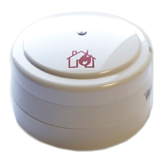
The Ziton wireless remote indicator and ancillary
equipment are available under the following part
numbers:
PART NO
VARIANT TYPE
ZR4-RL
Ziton wireless remote indicator
c/w wireless base
ZR401-RL
Ziton wireless remote indicator
base (no remote indicator)
ZX4-RL
Ziton wireless remote indicator
(no wireless base)
The address of the unit is set when programming the
device to the system (see commissioning manual for
details). The installation must conform to BS5839: Part 1
(or applicable local codes).
Installation of Ziton wireless remote indicator
Ensure that all detectors are sited in accordance with the
survey and design details.
First disengage the remote indicator from the wireless
module by turning it counter clockwise. This exposes the
user features in the wireless module, see Figure 2.
Disengage the mounting plate by pressing down the
locking pin, see Figure 2, and turn the wireless module
counter clockwise whilst pressing it against the
mounting plate.
This dis-assembles the mounting plate from the wireless
module and remote indicator sections, see Figure 1. The
mounting plate is now free to be xed to the wall or
ceiling.
To guarantee correct operation, connect the power
jumper across the PIN header on the wireless module
located under the remote indicator, see Figure 2.
©2015 EMS Security Group Ltd. All rights reserved
Mounting Plate
Wireless Module
Remote Indicator
Wireless RIM Base
Part No: ZR401-RL
0359-CPR-00424
EN54-25: 2008
Technical Data refer to Installation guide
3.5 - 4.5V DC
3.5 - 4.5V DC
0.2 - 300mA
0.2 - 300mA
1W Max
1W Max
PRESS HERE TO
PRESS HERE TO
LOG ON
LOG ON
Power jumper
Ident
Locking mechanism
Fix Mounting Plate
Fix the mounting plate using suitable xings and
fasteners. All four mounting holes must be used, see
Figure 3 for highlighted mounting holes.
When wall mounting, to ensure the text
!
description of the head is shown correctly, the
mounting plate should be installed in the orientation
shown in Figure 3.
It is important that fastener heads are ush or sub- ush
with the internal surface of the ceiling mount to avoid
the risk of damaging the battery PCB.
1 / 4
TSD170 Iss 2 27/07/15 AJM
Figure 1
Figure 2
Advertisement

Subscribe to Our Youtube Channel
Related Manuals for Ziton ZR4-RL


Summary of Contents for Ziton ZR4-RL
- Page 1 Notes Ziton Wireless Remote Indicator Installation Guide General The Ziton wireless remote indicator and ancillary equipment are available under the following part numbers: PART NO VARIANT TYPE ZR4-RL Ziton wireless remote indicator c/w wireless base Mounting Plate ZR401-RL Ziton wireless remote indicator...
- Page 2 Battery tment Dimensions 113mm (Ø) 40mm (D) www.recyclethis.info The Ziton Remote Indicator is powered by 6 x AA alkaline (No remote indicator) batteries. These are supplied tted. Should batteries 113mm (Ø) 90mm (D) require replacement, only use speci ed batteries whilst...
Need help?
Do you have a question about the ZR4-RL and is the answer not in the manual?
Questions and answers