Advertisement
Quick Links
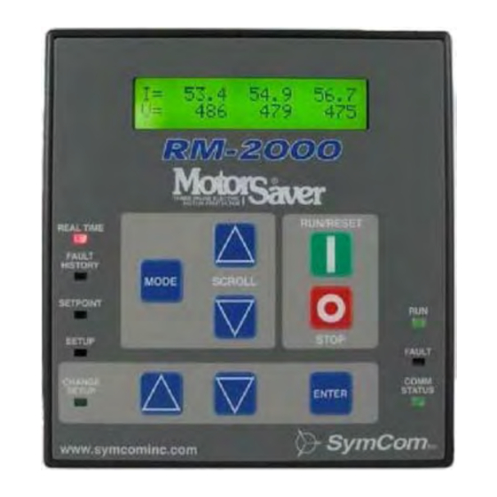
The RM-2000-RTDW motor-monitoring device can be used to monitor and/or control
SymCom's Model 777 via an RS-485 Modbus network. Two form C output relays are
available for an RTD alarm and a warning alarm. Alarm and trip levels can be set for each
RTD to activate the RTD alarm and deactivate the 777 output relay respectively.
In addition, the RM-2000-RTDW has two inputs: one to connect to a ground-fault module
and the other for connection to a remote reset button.
A second communication port allows monitoring and control of up to 99 RM-2000-RTDW
devices from a computer with SymCom's Solutions software, or a PLC, DCS, or SCADA
system. The RM-2000-RTDW is environmentally protected and can easily be mounted on
the front of a panel or MCC.
The RM-2000-RTDW displays the following
motor information:
• Real-time line currents, average current
and current unbalance
• Current to ground
• Line-to-line voltages, average voltage
and voltage unbalance
• Instantaneous power
• Power factor
• Last four faults
• All programmed 777 settings
• Remaining restart delay times
• 8 RTD temperatures
• Warning settings
The RM-2000-RTDW is also equipped with a
real-time clock, which allows access to the
following motor management information:
• Total motor run-time (reset capable)
• Time and date of last four faults, with voltage and current at time of trip
• Time and date of last ten motor starts
• Total number of motor restarts (reset capable)
• Minimum time between any two starts with time and date
• Run-time since last start (reset capable)
• KWhs consumed
• KVARs consumed
Phone: 800.894.0412 - Fax: 888.723.4773 - Web: www.clrwtr.com - Email: info@clrwtr.com
RM-2000-RTDW
Remote Monitor
User's Guide
Advertisement

Related Manuals for SymCom Motor Saver RM-2000-RTDW

Summary of Contents for SymCom Motor Saver RM-2000-RTDW
- Page 1 The RM-2000-RTDW motor-monitoring device can be used to monitor and/or control SymCom’s Model 777 via an RS-485 Modbus network. Two form C output relays are available for an RTD alarm and a warning alarm. Alarm and trip levels can be set for each RTD to activate the RTD alarm and deactivate the 777 output relay respectively.
- Page 2 PART I INSTALLATION AND OPERATION FEATURES The RM-2000-RTDW is a motor management device used in conjunction with any SymCom Model 777. The RM-2000-RTDW provides the following features: Information Displayed · Run-Time Information: the RM-2000-RTDW can display all of the information...
- Page 3 INSTALLING THE RM-2000-RTDW 1. Attach the template drawing to the panel where the RM-2000-RTDW is to be mounted. 2. Take caution when drilling the holes to mount the RM-2000-RTDW. Use an 11/64” drill bit for the four corner mounting screws. Drill a 1 15/16” – 2 3/16” hole for the terminals to protrude through to the inside of the panel.
- Page 4 WARNING ALARM ALARM NO2 C2 NO1 C1 115VAC REMOTE RTD MODULE ADDRESS RS-485 MODBUS MASTER: PC, PLC, RUN/RESET REAL TIME DCS, or SCADA FAULT HISTORY MODE SCROLL SETPOINT 24VDC STOP SETUP F AULT MODEL 777 COMM CHANGE STATUS SETUP ADDRESS #1 ENTER MODEL 777 DISPL AY / PROGRAM...
- Page 5 The RM-2000-RTDW has a second RS-485 port allowing connection to a network host, such as a PLC, DCS, or SCADA system or a PC running Modbus master software such as SymCom’s Solutions. The network host is not required. If present, the network host must be connected to Comm Port 2 at the connections labeled A2 and B2.
- Page 6 OPERATING THE RM-2000-RTDW RM-2000-RTDW information and functions are divided into five modes: • REAL TIME • FAULT HISTORY • SETPOINT • SETUP • CHANGE SETUP (key switch or jumper required) Press the [MODE] button to switch between these modes. An LED on the left side of the RM-2000-RTDW indicates which mode is selected.
- Page 7 LEDs Eight LEDs indicate the status of the RM-2000-RTDW: • five red LED’s on the left side indicate the display mode • the green COMM STATUS LED on the lower right indicates the communication status between the RM-2000-RTDW and the Model 777 and RTD module. If the COMM STATUS LED is: On –...
-
Page 8: Real Time Mode
PART II - SCREEN INFORMATION REAL TIME MODE The REAL TIME mode displays real-time information as well as calculated power factor and power consumption, and total number of starts and trips. By scrolling through the REAL TIME mode the following screens can be viewed: Current and Voltage Information - displays line-to-line voltages and phase currents. - Page 9 Accumulated Hours and Energy A C C . H O U R S = 0 . 1 E N E R G Y - K W H = 3 . 0 The Accumulated Hours is the number of hours the Model 777 has detected current flow and the Energy-kWh (or Energy-MWh) is the calculated energy consumed during these hours.
- Page 10 Pending Fault Information P E N D I N G F A U L T N O N E The Pending Fault screen will display up to three pending faults the Model 777 has sensed. The RM-2000-RTDW’s FAULT LED will blink anytime a pending fault condition exists.
- Page 11 Fault Voltage Unbalance and Average Voltage - reported just before the fault. F A U L T V . U N B A L = A V E R A G E V O L T . = 2 3 0 Fault Ground Fault Current - reported just before the fault.
-
Page 12: Setpoint Mode
SETPOINT MODE The SETPOINT mode displays the parameters that are programmed into the Model 777. Each setting can be viewed and changed using the RM-2000-RTDW, without interrupting the Model 777’s control relay. Current Limits – overload and underload limits. O V E R C U R R . -
Page 13: Setup Mode
Writing: the value to be written is displayed as both hexadecimal and decimal numbers. Set the proper address, scroll to show “WRITE,” and press [ENTER]. Reading: set the address, show “READ,” press [ENTER]—the value will be displayed, *Please refer to SymCom’s 777 Programming Guide for more information. Command Line S e n d... - Page 14 The host network allows communication between an RM-2000-RTDW and a PC with SymCom’s Solutions software, or a PLC, DCS, or SCADA system. Up to 99 RM-2000s can exist on this network; thus, the network address can be set from A001–A099.
- Page 15 Remote RTD Module Comm Port (Port 1, A1 & B1) Remote RTD Module Address - can be set from 16 to 23. R E M O T E R T D ( P O R T R T D A D D R E S S : The RTD Address must match the address selected on the RTD module.
- Page 16 Starting with Voltage Errors* S T A R T I N G W / V O L T . E R R O R S : S E N D O F F This setting controls how a [RUN/RESET] button* is handled when the Model 777 is trying to start, but voltage errors are present.
- Page 17 Minimum Time Between Starts M I N I M U M T I M E B E T W E E N S T A R T S : M I N U T E S The Minimum Time Between Starts (MTBS) can be set from 0–60 Minutes. Each time the motor starts, the Minimum Time Before Next Start (FAULT HISTORY mode) begins counting down from the MTBS setting.
- Page 18 Output Relay Status - displays the status of the RM-2000-RTDW output relays. R E L A Y O F F R E L A Y O F F This screen is only visible if the I/O Screens are set to ON. I/O Screens - displays/hides the input and output relay status screens.
- Page 19 Firmware Version R M - 2 0 0 0 - R T D W V e r s i o n 3 . 1 5 This screen is only displayed in the SETUP mode. It displays the firmware version number and any options that the firmware is configured to control. CHANGE SETUP MODE The CHANGE SETUP* mode allows changes to be made to the SETPOINT and SETUP information.
- Page 20 RM-2000-RTDW SPECIFICATIONS 115VAC ±10%, 50 or 60Hz Control Voltage Transient Protection 2500V for 10ms Power Consumption 3 Watts (max.) Communication MS 777 RTD Module PC, PLC, etc. Baud Rate 9600 300-28800 300-28800 Even Parity, None, Odd, or Even None, Odd, or Even Setup 1 Stop Bit Parity, 1 or 2 Stop Bits...
Need help?
Do you have a question about the Motor Saver RM-2000-RTDW and is the answer not in the manual?
Questions and answers