
Subscribe to Our Youtube Channel
Related Manuals for Rheem Lazer Classic Series


Summary of Contents for Rheem Lazer Classic Series
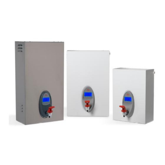
- Page 1 Part No. 316935A OWNERS GUIDE & INSTALLATION INSTRUCTIONS CLASSIC SERIES POWDER COATED Models 3, 5, 7.5, 10, 15, 25, & 40 Litre STAINLESS STEEL Models 7.5, 10, 15, 25, & 40 Litre IMPORTANT, PLEASE LEAVE WITH THE OWNER...
-
Page 2: Table Of Contents
CONTENTS 1. WARNING ..................... 3 2. WATER QUALITY ..................3 3. INSTALLATION ..................... 3 A. Location ....................3 B. Opening the Unit ..................3 C. Minimum Clearance ................3 D. Mounting ....................3 E. Water Supply Connection ..............3 F. Overflow / Vent Connection Importance ..........4 G. -
Page 3: Warning
For further information relating to the WARNING: guidelines of water quality, contact your Before drilling into the wall make sure local Rheem office for advice. that the screw positions avoid any pipe- 3. INSTALLATION work or electrical cables. Allow 4 mm... -
Page 4: Overflow / Vent Connection Importance
(note switch unit off before draining) IMPORTANT Installation and maintenance of the Lazer Boiling Water unit shall be carried out by a qualified service person. Your closest Rheem Service Centre can be contacted by telephoning 0800 657 335... -
Page 5: Tap Outlet
H. TAP OUTLET 4. OPERATION To prevent damage during transport the tap is wrapped and placed inside the unit When the installation is complete, first enclosure near the solenoid valve & vent turn water supply before fittings. The tap is connected to the tap switching on the power. -
Page 6: Mounting Dimension Specification For All Models - Drawing
DIMENSION SPECIFICATION Classic models Figure 4: Dimension Specification 3 Litre 5 Litre 7.5 Litre 10 Litre 15 Litre 25 Litre 40 Litre Dimension A mm B mm C mm D mm E mm F mm G mm H mm N mm M mm... -
Page 7: Dimension Specification For All Models - Drawing
SPECIFICATION 3 Litre 5 Litre 7.5 Litre 10 Litre 15 Litre 25 Litre 40 Litre Classic Series Approx Weight (kg) Empty Approx Weight (kg) Full Minimum Water Pressure kPa Maximum Water Pressure kPa 1000 1000 1000 1000 1000 1000 1000 Element Size kW Figure 2: Overflow / Vent Connection MOUNTING DIMENSION SPECIFICATION... -
Page 8: For Units With A Timer
B) Set Timer to STD/AUTO Mode 5. For Units With a Timer Select the Timer STD/AUTO mode Timer Functions (Prog>Timer STD/AUTO>Accept) Clock Display Shows: “STD” Timer STD/AUTO Pressing the (UP) button alternates the C. Set Sleep Delay Time* “STD”/“AUTO” icons. operation D. -
Page 9: Filter Life
Display Shows: “SUN” “7:00 – 7:00” Select Appropriate Service Mode “Set OFF hour”. Error Codes Boiling Temp Press the (UP) button until the desired iii. Chiller Temp hour appears on the screen and press the Calib Reset (Accept) button to confirm selection. Software Version Display Shows: “SUN”... -
Page 10: For Units Without A Timer
6. For Units Without a Timer Decal Functions D) Ready LED (Green) A) Cal Reset Button B) Filter Reset Button The green Ready LED shows the status C) Power LED (Red) of the water temperature within the D) Ready LED (Green) Boiling Water Unit. -
Page 11: Fault Finding Guide
LAZER BOILING WATER UNIT: FAULT FINDING GUIDE. **It is strongly recommended that any REMEDY be carried out by a qualified service person** SYMPTOMS POSSIBLE CAUSE REMEDY There is no power supply Check the electrical supply. There is no water supply Check the water supply. -
Page 12: Warranty Information
3. Where the boiling water unit or its component has failed directly or indirectly as a result of high water pressure. 4. Where the boiling water unit is located in a position that does not comply with the Rheem installation instructions or relevant statutory requirements causing the need for major dismantling or removal of cupboards.
Need help?
Do you have a question about the Lazer Classic Series and is the answer not in the manual?
Questions and answers