Table of Contents
Advertisement
Quick Links
Advertisement
Table of Contents

Summary of Contents for FitLux 9950
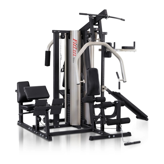
- Page 1 9950 MULTIGYM...
-
Page 2: Table Of Contents
INDEX: IMPORTANT NOTICE ........P. 1 IMPORTANT SAFETY WARNINGS . -
Page 3: Important Notice
inch IN-LINE WITH UNDERSIDE OF HEAD BOLT LENGTH INDICATOR NOTE: Bolt lengths are manufactured in metric(mm) so imperial length (inches) is approximate. eg. 65mm = 2-1/2" IMPORTANT NOTICE: Read the instructions carefully before beginning installation. Thank you for choosing this unit for muscular activity. -
Page 4: Important Safety Warnings
IMPORTANT SAFETY WARNINGS PRECAUTIONS This exercise equipment is manufactured for use in perfect safety. However, certain precautions should be applied whether you operate a piece of equipment. For this we recommend that you read the entire manual before beginning installation of your equipment. In particular, read the following safety precautions: 1. -
Page 5: Drawing Of Main Body
DRAWING OF MAIN BODY... -
Page 6: Exploded Drawing O F Main Body
EXPLODED DRAWING O F MAIN BODY 41 40... - Page 7 1090MM 3050MM 3470MM 5000MM...
-
Page 8: Assembly Parts List Of Main Body
ASSEMBLY PA RT S LIST OF MAIN BODY LEG EXTENSION SUPPORT MAIN POLE CHEST PRESS PIPE SUPPORT TUBE END BASE BRACE CENTER BASE BRACE SIDE BASE BRACE BACK PAD TOP CROSS BEAM SEAT SUPPORT BRACE SEAT PAD LEG EXTENSION BRACE SEAT SUPPORT TUBE U BRACKET ADJUSTING BRACKET... - Page 9 ASSEMBLY PA RT S LIST OF MAIN BODY 3/8"X76L FORM PAD 30X70 3/8"XΦ19X1.0t M6X16L PIN FOR WEIGHT STACK M8X45L Φ8.2xΦ16X1.5t 3/8" 30X70 CURLING BAR PLASTIC INNER BUSHING 30X60 QUICK PIN PLASTIC INNER BUSHING 50X50 PLATE GRIP COVER 3/8" 5/8"X254L 3/8"X128L METAL BUSHING 40X80 3/8"X89L...
- Page 10 ASSEMBLY PA RT S LIST OF MAIN BODY INNER PIPE LOW PULL BAR WEIGHT PLATE ROLLER PIPE PLATE PULLEY 23X53 3/8"X32L GUIDE PIN 3/8"X38L 3/8" 1/2"X76L 3050MM 1" CABLE SAFETY COVER 1090MM 1/2" METAL BUSHING GUIDE ROD CABLE 1/2" SNAP HOOK 3470MM 5000MM FLOATING PULLEY BLOCK...
-
Page 11: Main Body Assembly Instructions
MAIN BODY ASSEMBLY INSTRUCTIONS STEP 1: 1. Put CAP (5) onto END BASE BRACE (C) and SIDE BASE BRACE (E). 2. Attach MAIN POLE (A), SUPPORT TUBE (B) and END BASE BRACE (C) onto CENTER BASE BRACE (D) by screwing on parts ( 1,2,4 & 10 ) provided. - Page 12 STEP 2: 1. Put TOP CROSS BEAM (F) on top of MAIN POLE (A), securing with parts (2, 4,7 & 10) provided. Connect TOP CROSS BEAM (F), SUPPORT TUBE (B) and TOP CROSS BRACE (K) by screwing on parts (2,4 & 8) provided. 2.
- Page 13 STEP 3: 1. Attach LEG EXTENSION SUPPORT (P) onto LEG EXTENSION BRACE (H) and MAIN POLE (A) by screwing on parts (1,2,4,7 & 10) provided. Insert into PLASTIC INNER BUSHING (27), then screw on QUICK PIN (16). Put on CAP (28) on top of LEG EXTENSION SUPPORT (P). 2.
- Page 14 STEP 4: 1. Insert METAL BUSHING (20) into PRESS HOLDER (O) first, and then attach CHEST PRESS PIPE (Q) onto PRESS HOLDER (O) by screwing on parts (29 & 31) provided. NOTE: DO NOT tighten the bolts rmly yet. Insert PLASTIC INNER BUSHING (22) and put on GRIP COVER (17). 2.
- Page 15 STEP 5: 1. Insert METAL BUSHING (39) into the top of LEG EXTENSION TUBE (W), have LEG EXTENSION TUBE (W) attached onto the top of LEG EXTENSION SUPPORT (P), securing with parts (40, 41 & 57) provided. NOTE: DO NOT tighten the bolts rmly yet. 2.
- Page 16 STEP 6: CABLE AND PULLEY ASSEMBLY INSTRUCTION: Start threading with CABLE (48). 1. Refer to Drawing (A1 & A2), have one end of CABLE (48) screwed on the bolt on left PEC DECK ARM (M). 2. Thread CABLE (48) through the pulleys in order of P1-P2 then up to P3. NOTE: 1) Cable and pulleys must be threaded and assembled at the same time.
- Page 17 STEP 7: CABLE AND PULLEY ASSEMBLY INSTRUCTION: A. Start threading with CABLE (50): Refer to Drawing (A1), have CABLE (50) head (without the ball over) threaded through Pulley (P9). NOTE: Cable and pulley must be threaded and assembled at the same time. B.
- Page 18 STEP 8: CABLE AND PULLEY ASSEMBLY INSTRUCTIONS: Start threading with CABLE (51): 1. Refer to Drawing (A1), thread CABLE (51) head (without the ball over) through the pulleys in order of: P1-P2-P3-P4-P5-P6-P7-P8 NOTE: 1) Cable and pulleys must be threaded and assembled at the same time. 2) Assemble and attach pulleys as per each exploded drawing shown: A1, A2, A3, A4 &...
-
Page 19: Drawing Of Main Body & Bench / Vkr
DRAWING OF MAIN BODY & BENCH / VKR... -
Page 20: Exploded Drawing Of Bench & Vkr
EXPLODED DRAWING OF BENCH & VKR... -
Page 21: Assembly Parts List Of Bench & Vkr
ASSEMBLY PARTS LIST OF BENCH & VKR SIT UP BENCH VKR MAIN POLE VKR BASE BRACE BACK PAD ARM PAD PUSH UP FRAME ROLLER PAD REINFORCEMENT FITTING ROLLER PAD PIPE FITTING PLASTIC INNER BUSHING VKR TOP CROSS BEAM VKR HANDLE BAR 3/8"X1”L M8X56L LEG CURL AXLE... - Page 22 ASSEMBLY PARTS LIST OF BENCH & VKR 1/2" Φ10.5XΦ35X3.0t 3/8"X76L METAL BUSHING 1/2" Φ8.2xΦ16X1.5t 3/8"XΦ19X1.0t 1/2" 3/8" GRIP COVER 50X50 1/2"X76L 1" 3/8"X70L...
-
Page 23: Vkr & Bench Assembly Instructions
VKR & BENCH ASSEMBLY INSTRUCTIONS STEP 1: 1. Attach VKR BASE BRACE (C2) onto SIDE BASE BRACE (E) by screwing on parts (1,2,4 & 10) provided. 2. Connect PUSH UP FRAME (D2) and VKR BASE BRACE (C2), securing with parts (1,2 & 4). Put on CAP (5) and GRIP COVER (17) onto PUSH UP BAR as drawing shown. - Page 24 STEP 2: 1. Attach VKR TOP CROSS BEAM (H2) onto TOP CROSS BRACE (X) and top of VKR MAIN POLE (B2), securing with parts (1,2,4 & 10) provided. 2. Attach VKR FRAME (I2) onto VKR MAIN POLE (B2) by screwing on parts (1,2 & 4) provided. 3.
-
Page 25: Drawing Of Main Body , Bench /Vkr & Leg Press
DRAWING OF MAIN BODY , BENCH /VKR & LEG PRESS... -
Page 26: Exploded Drawing Of Leg Press
EXPLODED DRAWING OF LEG PRESS 41 40 1510MM 3380MM... -
Page 27: Assembly Parts List Of Leg Press
ASSEMBLY PARTS LIST OF LEG PRESS LEG PRESS END BASE BRACE SEAT FRAME LEG PRESS CENTER BASE BRACE LEG PRESS POST LEG PRESS CENTER BASE BRACE ARM CURL POST LEG PRESS SIDE BASE BRACE SEAT REST TOP CROSS BRACE ARM CURL PAD TOP CROSS BEAM SEAT PAD SEAT SUPPORT TUBE... - Page 28 ASSEMBLY PARTS LIST OF LEG PRESS 3/8" 3/8"X76L METAL BUSHING WEIGHT PLATE 3/8"XΦ19X1.0t CURLING BAR PULLEY 50X50 PIN FOR WEIGHT STACK Φ13XΦ44X3.0t 3/8" CHAIN M8X16L GUIDE PIN 3/8"X70L 1/2"X76L 30X60 3/8"X38L Φ10.5XΦ35X3.0t SAFETY COVER 1/2" M6X16L METAL BUSHING GUIDE ROD 1/2"...
- Page 29 STEP 2: 1. Insert GUIDE ROD (59) into LEG PRESS SIDE BASE BRACE (D1) and slip on RUBBER WEIGHT STACK BOTTOM (62). 2. Slip on WEIGHT PLATE (44) into GUIDE ROD (59) one by one, then TOP PLATE (43). Insert ROD (52) into the top hole of GUIDE PIN (56), and insert the GUIDE PIN (56) into the central hole of TOP PLATE (43) to secure.
-
Page 30: Leg Press Assembly Instructions
LEG PRESS ASSEMBLY INSTRUCTIONS STEP 1: 1. Put CAP (5) onto end of LEG PRESS END BASE BRACE (A1) and SIDE BASE BRACE (D1). 2. Release the assembled parts (1,2 & 4) from CENTER BASE BRACE (D) to attach LEG PRESS CENTER BASE BRACE (B1) and SIDE BASE BRACE (D1) onto CENTER BASE BRACE (D), re-screwing on the parts (1,2,4 &... - Page 31 STEP 3: 1. Attach LEG PRESS MAIN POLE (J1) onto CENTER BASE BRACE (C1) by screwing on parts (1,2 & 4) provided. 2. Connect TOP CROSS BEAM (F1) and TOP CROSS BRACE (E1) with parts (1,2 & 4) provided. Put another end of TOP CROSS BEAM (F1) onto top of MAIN POLE (J1), securing with parts (1,2 &...
- Page 32 STEP 4: 1. Insert PLASTIC INNER BUSHING (W1) into SEAT REST WITH HANDLE BAR (P1). Insert SEAT FRAME (M1) into SEAT REST WITH HANDLE BAR (P1). Put the PLASTIC INNER BUSHING (V1) on the end of SEAT FRAME (M1), have the SEAT FRAME (M1) slipped on SEAT SUPPORT TUBE (G1), securing with parts (2,4 &...
- Page 33 STEP 5: CABLE AND PULLEY ASSEMBLY INSTRUCTIONS 1. Start threading with CABLE (U1): Thread CABLE (U1) through the pulleys in order of: P3-P4-P5-P6-P7-P8-P9 NOTE: 1) Cable and pulleys must be threaded and assembled at the same time. 2) Assemble and attach pulleys as per each exploded drawing shown: A4, A5, A6, A7 &...
-
Page 34: Drawing Of Whole Unit
DRAWING OF WHOLE UNIT... -
Page 35: Workout Chart
WORKOUT CHART Lat pull Lat pull Leg extension Leg press Push Up Lat Pull Lat Pull Arm Curl Sit up Low Pull Lat Pull Rear deltoid Butterfly Abdominal Crunch Vertical knee raise Chest press... - Page 36 201512 01...
Need help?
Do you have a question about the 9950 and is the answer not in the manual?
Questions and answers