
Subscribe to Our Youtube Channel
Related Manuals for DynaQuip WaterCop Pro WPK Series

Summary of Contents for DynaQuip WaterCop Pro WPK Series
- Page 1 Owner’s Manual and Installation Guide The proven leader in household leak protection: WaterCop® is there when you’re not.
-
Page 2: Table Of Contents
Table of Contents System Description . . . . . . . . . . . . . . . . . . . . . . . . . . . . . . . . . . . . . . . . . . . . . . . . . . . . . . . . . . . . . . 2–3 System Components . -
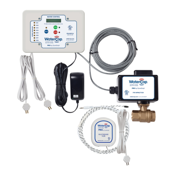
Page 3: System Components
always be placed indoors . Contact us if you have any questions about the placement of your WaterCop® Pro . Check the contents of the carton with the products listed on the carton label . The shipping package should contain the following: •... -
Page 4: General Safety Information
Hardwired Sensor Probes: 10' white cord with single sensor probe . WaterCop® Pro sensor probes are easily secured to the surface using adhesive or the mounting holes . Hardwired sensors provide the same feedback to the Water Control Panel as the WaterCop® Pro wireless sensors . Use hardwired sensor probes for convenience, or if conditions prevent wireless communication . -
Page 5: Safe Mode Instructions
into direct contact with a leak sensor’s probe, an RF signal is transmitted to the Water Control Panel and the valve closes, turning off the water source to protect the building from additional water damage . The red indicator light will signal that the valve is now in the closed position . The valve will remain closed until the unit is manually reset (through the manual override handle or the OPEN button on the Water Control Panel) . -
Page 6: Fcc Information
FCC Information This equipment has been tested and found to comply with the limits for a Class 8 digital device, pursuant to part 15 of the FCC Rules . These limits are designed to provide reasonable protection against harmful interference in a residential installation . This equipment generates, uses, and can radiate radio frequency energy and if not installed and used in accordance with the instructions, may cause harmful interference to radio communications . -
Page 7: To Power And Program Wireless Sensors
. The WaterCop® Pro System is capable of supporting as many as 45 wireless sensors . Wireless sensors, up to 45 total, can be added in the future by repeating the steps taken in this section . Please contact your local dealer or DynaQuip® Controls to inquire about additional sensors . -
Page 8: To Remove Sensors
To Remove Wireless Sensors To Enable Safe Mode If you need to remove a wireless sensor for Close the valve then press and hold down any reason, follow these instructions: the MODE button . While holding the MODE button, press OPEN, then release •... -
Page 9: Wireless Wpm Hub Sensor And Accessories
Wireless WPM Hub Sensor and Accessories Onboard Temperature WPM: This is what is considered the “Hub” . It Sensor – Trip Point 45°F requires AAA Alkaline batteries (or the optional AC Adapter) and wirelessly communicates with the Pro Control Panel . Sensor probes and other accessories are attached to the Hub in many different configurations . -
Page 10: Manually Testing The Valve And Wireless Sensors
Extension (WEXT6) WEXT6: This wireless sensor accessory has a male plug that AC Adapter inserts into the AUX jack on the WPM and has a female jack on the (ACA100) other end to give an extra 6' length so a rope or pressure sensor can be extended further away from the WPM Hub . -
Page 11: Troubleshooting
2 . At one of the locations you have chosen to monitor, drop the sensor probe (not the mounted transmitter) into a cup of water . Hold until you hear the sensor transmit a signal to the Water Control Panel and close the valve (about 15 seconds) . This test simulates a leak and lets you check for interference between the sensor and the Water Control Panel . -
Page 12: Range Enhancing Repeater
The transmitter in the wireless sensors and the receiver in the Water Control Panel communicate by radio frequency . The smaller the distance between them, the stronger the signal will be . Transmission distance is somewhat dependent upon the building layout and the type of construction . -
Page 13: Installation Procedure: Indoor Vs. Outdoor
battery condition to the Control Panel . In the event the battery power reaches a critically low status, a CLOSE signal will be transmitted to the WaterCop® valve as a precaution . After replacing batteries, re-test each unit in its regular location . Periodic testing of sensors is required to monitor proper power and function . -
Page 14: Compression Fittings
Compression Fittings The unit can be installed with compression fittings using common household tools and basic mechanical ability . You will need: • two fittings (male pipe thread x compression) • tubing cutter; available at most local hardware or plumbing •... -
Page 15: Emergency Procedures
Emergency Procedures In the unlikely event that the WaterCop® Pro System should shut off the main water supply and then become inoperable due to a power outage or damage, it is possible to manually operate the WaterCop® Pro to return water service . Unplug the Water Control Panel from its power source . - Page 16 Maintenance Log Visit WaterCop.com for your warranty information. Made in the USA To order or for additional information, visit watercop.com or call 800-545-3636. 192446 REV H...
Need help?
Do you have a question about the WaterCop Pro WPK Series and is the answer not in the manual?
Questions and answers