
Related Manuals for Motas 6


Summary of Contents for Motas 6
- Page 1 User Guide document version 1.29 (non-printed) for firmware version 06020119 January 31, 2021...
-
Page 2: Table Of Contents
Contents Foreword Proper use and maintenance. Document conventions Introduction Top and rear panel Quick-start Control Overview Parameter pages Parameter page display overview Modulation. Global Modulation Sources Low-Frequency Oscillator (LFO) waveforms Global Low-Frequency Oscillators (LFOx) Dedicated Low-Frequency Oscillators (LFO) Envelope Generators (EG) Editing parameters with rotary knobs Parameter pages - in depth 10.1... - Page 3 10.5 Mixer section 10.6 Low-pass filter 1 10.7 High-pass filter 10.8 Low-pass filter 2 10.9 Output stage Patch summary 11.1 Parameter mapping Load, Save and Copy/Reset/Randomise 12.1 Load patch 12.2 Save and erase patches 12.3 Copy/Reset/Randomise Vector morphing Arpeggiator 14.1 Main arpeggiator settings 14.2...
- Page 4 17.4 Parameter mapping 17.5 MIDI channels 17.6 Modulators. 17.7 EG Triggers 17.8 Morph/patch change 17.9 CV/Gate inputs 17.10 CV/gate offset and scaling. 17.11 Tuning 17.12 SysEx data backup 17.13 Param map control 17.14 NRPN / SysEx/ THRU 17.15 Poly chain 17.16...
-
Page 5: Foreword
(gratefully received) please email support@motas-synth.uk. Whilst every effort has been made to ensure that this guide is as accurate as possible Motas Electronics Limited will not be liable for any erroneous information. This manual may be updated at any time without prior notice. Please check the website for updates. -
Page 6: Proper Use And Maintenance
Please read the following instructions care- sound. Any other use is prohibited. Motas Electronics fully and keep them with the apparatus. Do not op- Limited is not liable for damages due to incorrect use. -
Page 7: Document Conventions
Document conventions You will find many screenshots taken from throughout this guide. An example is shown below: The following document formatting conventions are used: • Link (blue text) is a weblink or a link to another part of this document. •... -
Page 8: Introduction
• Three independent analogue filters (VCFs) with flexible justable resonance to self-oscillation (with selectable 1, 2, routing: 3, 4, 5 and 6-pole outputs), a 2-pole high-pass filter and a second 4-pole low-pass filter with adjustable resonance to – Low-pass resonant filter (6-pole with selectable out- self-oscillation. - Page 9 Integration with external software Free software including DAW plugin software is available Dedicated analogue rotary potentiometers are used to download from www.motas-synth.uk/downloads.html. to access the basic analogue parameter pages and to al- This allows live control between and your low fast ’tweaking’ in real-time. In addition...
-
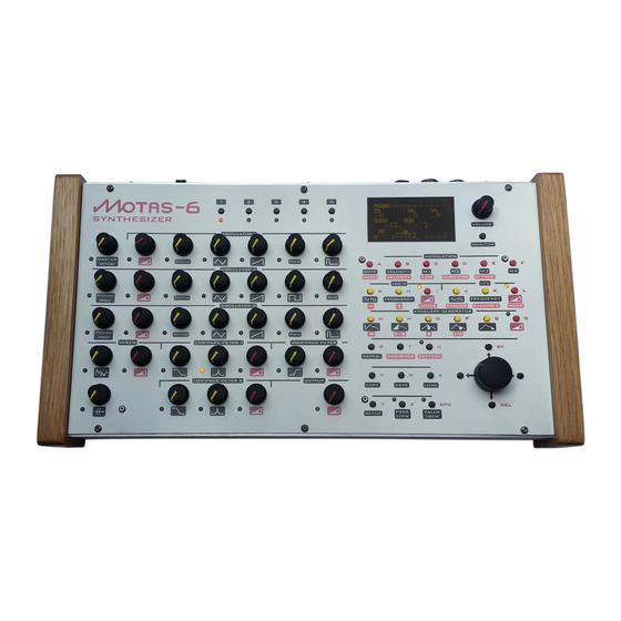
Page 10: Top And Rear Panel
[ USB type-B ] headphones out (2 channel mono) power supply in [ Stereo 6.35mm phone socket ] [ 2.1mm. 12V DC, 1A, centre positive ] main audio out (mono) power on/off push switch [ Mono 6.35mm phone socket ]... -
Page 11: Quick-Start
4. Plug in the 12V DC power supply into connection 5. Turn on using the power button The display will show the start-up image. 6. Press (in the group) and then the monitor right arrow button . The display will change... -
Page 12: Control Overview
Control Overview To access the settings (parameters) that determine the sound page turn the appropriate rotary knob . The active you turn a rotary knob corresponding to the setting parameter page is shown by the adjacent flashing LED. that you want to change. Each rotary knob is associ- Fast patch changing ated with it’s own ’parameter page’. - Page 13 has a parameter mapping feature that can be used to send and receive simple MIDI CCs to control up to 24 patch parameters. See section 17.4. CHAPTER 7. CONTROL OVERVIEW page 9 User Guide v1.29...
-
Page 14: Parameter
Parameter pages The sound generated by is controlled by triangle waveform the settings on 33 parameter ’pages’ – each parameter has volume level its own ’page’ shown on the display. These are listed below sawtooth waveform and explained in detail in chapter 10. To access a particu- volume level lar parameter page turn the appropriate rotary knob square waveform... -
Page 15: Parameter Page Display Overview
• pages: low-pass filter 2 cut-off frequency and input routing options resonance amount output volume level and routing options • page: output output volume level and Page title clipping options Each page has a ’destination’ i.e. what aspect of the syn- thesizer it controls, and this is labelled at the top left of the display. - Page 16 encoder to change the value. Press When the parameter page displays simultaneously to jump to the first option. Press modulations not active again, or press simultaneously the current value will follow the basic offset, since to return to the main parameter page. all the modulations amounts are set to zero.
-
Page 17: Modulation
’drone’ sound patch. 9.1 Global Modulation Sources There are 6 MIDI / CV / Global modulation sources avail- Each and every parameter page has dedicated modulation able on each parameter page: MIDI note-on value (or CV... - Page 18 second row. Each modulation source has two amount settings. The first (primary) sets the amount of the modulation signal to add or subtract to the parameter page basic offset e.g if set on the parameter page it would directly lpf-1 :freq increase or decrease the cut-off frequency of low-pass fil- ter 1 as the modulation signal increases or decreases.
- Page 19 See sec- The note pitch modulation signal is derived tion 17.6 for how to setup these global modulation sources. from the ’latest’ (i.e. most recent) note currently being played, including the effects of portamento, but excluding pitch-bend signals.
-
Page 20: Low-Frequency Oscillator (Lfo) Waveforms
very fast burst burst fast burst burst2 sine + sine at twice frequency sin+2 sine + sine at three-times frequency sin+3 half sin and half triangle combo sintri half triangle, half constant combo tri/2 modulated sine beat modulated sine variation beat2 The next 17 waveforms are primarily aimed at pitch modu- lation of the oscillators to play tuned notes (but of course... - Page 21 is unique to each page. In non pitch-tracking mode the frequency can be set from 0.001Hz – 452Hz (time period from 1000s to 2.2 ms). Press On the fourth row down on the display, on the left hand simultaneously to reset the frequency to side the settings for LFOx are shown.
-
Page 22: Dedicated Low-Frequency Oscillators (Lfo)
global4 Use pitch-tracking to apply a range of AM and FM effects (depending where the LFO is ap- LFO single-shot pled). Offset the pitch-tracking frequency to give characteristic noisy/complex tones. Since the LFOs cannot run at high audio rates (due to hardware the LFO runs continuously. - Page 23 LFO frequency will track as per pitch note values. There are 6 options: and also track the page. master pitch Output mode LFO frequency modulation LFO output level is not modulated.
-
Page 24: Envelope Generators (Eg)
– sets the time that the envelope falls from the sustain level (1 ms to 34.6 seconds). Press simultaneously to reset the values to defaults. to choose which EG option to edit and the rotary encoder to change the values. - Page 25 Gate/Trig This sets the source of the gate or trigger for the EG. Use the EG reset feature on percussion EG gate/trig on first note-on event, normal sounds where you want the EG cycle to always release phase starts when all notes are released. restart from zero and use the mode trigger...
-
Page 26: Editing Parameters With Rotary Knobs
EG level work in similar ways to EG shape lpf-2 Page offset output global LFO1 frequency master pitch 9.6 Editing parameters with rotary knobs global LFO2 frequency osc-2 phase mod global LFO3 frequency osc-3 phase mod are set enabled page lock... -
Page 27: Parameter Pages - In Depth
Parameter pages - in depth This chapter describes each parameter page in detail. The Although each waveform from oscillator 1 has it’s own level settings on each parameter page control the sound parameter page you can easily apply offset and modula- makes. - Page 28 pitch set to the last note on. last pitch set to the 1st or earliest can play paraphoni- note on. cally – you can play up to 3-note chords pitch set to the 2nd note on where each note of the chord is generated pitch set to the 3rd note on.
-
Page 29: Oscillator 2
osc-1 :sawtooth Phase-modulation is a form of waveform distortion where the phase of the waveform is This parameter page sets the volume level of the sawtooth changed over time. It is very similar to frequency wave output of oscillator 1. modulation but does not have the problems of pitch stability that can occur with frequency mod- The sawtooth wave has a rising and then... -
Page 30: Oscillator 3
pitch set to the last note on. last osc-2 :triangle pitch set to the 1st or earliest note on. This parameter page sets the volume level of the triangle pitch set to the 2nd note on wave output of oscillator 2. pitch set to the 3rd note on. - Page 31 pitch set to the last note on. osc-3 :phase mod last pitch set to the 1st or earliest phase mod note on. This parameter page sets the phase modulation depth for pitch set to the 2nd note on oscillator 3. The triangle, sawtooth and pulse waveforms pitch set to the 3rd note on.
-
Page 32: Mixer Section
osc-3 :triangle Use an EG to modulate the noise level to give a short burst of noise at the start of each note This parameter page sets the volume level of the triangle press to simulate percussive sounds. wave output of oscillator 3. This waveform can be phase-modulated to distort the wave- form from a pure triangle. -
Page 33: Low-Pass Filter 1
This filter is a very powerful low-pass filter with up to 6- pole roll-off (-36 dB per octave). It has adjustable reso- Each of these sound different - the 4-pole output gives a... -
Page 34: High-Pass Filter
1 pole 5. pole-5 low-pass filter 1 pole 6. pole-6 Low-pass filter 1 is constructed from a chain of 6 separate the noise source. noise filtering stages and the one selected for the final output low-pass filter 2. -
Page 35: Output Stage
1 pole 4. pole-4 low-pass filter 1 pole 5. pole-5 ’dry’: no clipping normal (dry) low-pass filter 1 pole 6. pole-6 distortion applied. the noise source. noise soft-clip enabled. soft clip the high-pass filter. -
Page 36: Patch Summary
Each of the boxes contains summary information corre- slot #5 osc-1 sponding to each of the 33 parameter pages. In feint on slot #6 osc-1 the far left of each box is shown a small horizontal bar that shows the rotary knob... -
Page 37: Load, Save And Copy/Reset/Randomise
Load, Save and Copy/Reset/Randomise allows up to 500 individual patches to be The load/save page remembers which patch saved and loaded (in addition to the patches saved with se- you last accessed so when you load or save again quences) and these are arranged into 10 ’folders’ or ’banks’. you will return to the same patch location. -
Page 38: Copy/Reset/Randomise
Reset page Press to select the reset page Press to erase the selected patch (you will be asked tion and then press to reset all parameters to de- to confirm by pressing fault values on the current parameter page. Reset patch 12.3 Copy/Reset/Randomise Select the option and then press... -
Page 39: Vector Morphing
Vector morphing mode only the continuously variable parameters are ad- justed (e.g LFO amount, offsets, EG attack), the discrete patch settings are not changed. To exit the vector morphing mode press . The blend at that point is automatically stored into slot #5. The name of the patch in slot #5 will be changed to where the xx values are the VM xx-xx-xx-xx... -
Page 40: Arpeggiator
Arpeggiator The arpeggiator feature allows to automat- • plays in ascending and then descending order updn ically play notes from a chord in succession with adjustable of pitch direction, number of octaves, pattern etc. The tempo is • plays in the order of the keys as played within determined from the current active clock setting see sec- each octave, but ascending octaves (when the range... -
Page 41: Internal Arpeggiator Settings
arpeggiator to automatically change patch on each new • dominant 7th chord (C ,Cdom dom7 note: • major 7th chord (CM major7 • augmented 7th chord (C+ ,Caug aug7 • patches are not changed M7+5 • augmented major 7th chord (C+ m7+5 •... -
Page 42: Pattern Sequencer
Pattern sequencer features a ’pattern sequencer’ which allows nominally 1 bar patterns to be created, edited and played. Each pattern can contain a series of notes, parameter changes and controller events. There are 96 time-steps per pat- tern. The start-time, pitch, velocity, duration, micro-tune and patch of each note can be adjusted. - Page 43 edit the note’s duration and To create new discrete or continuous events to edit the microtune (from 0 – 98 cents). micro-tune enter record mode and adjust the patch settings Press to edit the patch setting of the note. A patch as the pattern plays.
-
Page 44: Load/Save/Copy Patterns
6 clock ticks (0 – 8) 15.3 Load/save/copy patterns 15.5 Load/save sequences Patterns can be loaded and saved in much the same way as for patches (see section 12). There are 7 banks of pat- Sequences can be loaded and saved in much the same way terns each containing 8 patterns. -
Page 45: Monitor
Monitor Press to enter monitor mode. There are 4 monitor types of monitor mode: Volume level, MIDI, Oscilloscope and Spectrum Analyser. To leave monitor mode press another control button or turn a parameter control (when ’page-lock’ is not enabled). When monitor mode is enabled again the last selected mode is recalled. -
Page 46: Oscilloscope
2.5 ms (i.e. 2 thousandths of a second) per division. Press to pause/unpause the display (pause shown on the screen). Press to auto-scale the verti- cal display (shown by an on the screen). Note that the rescaling is limited and so for weak signals rescaling may not cause the waveform to fully fit the display. - Page 47 Press to pause/unpause the display (pause shown Internally the spectrum analyser feature on the screen). Press to auto-scale the verti- works by digital sampling of the audio signal over a cal display (shown by an on the screen). Note that the fixed time period.
-
Page 48: Setup
Setup The setup pages allow setting of a variety of operating set- sets whether the track note-off tings arranged over 16 pages. Press the button pitch of the oscillators can update and the envelope gen- setup to enter the setup pages. erators can re-trigger after note-off events. -
Page 49: Tempo Settings
sets the active clock source for any these buttons again to select which of the 4 custom wave- clk source forms to edit. synced LFOs, the arpegiator and the pattern/ sequencer. Choose for external MIDI (incoming on ext midi Each custom waveform has up to 32 steps in time. At each USB or MIDI in), for gate pulses on the CV/- ext clk... -
Page 50: Midi Channels
17.13. Note that if NRPNs G . The choice is from MIDI CC controllers plus chan- are enabled for any send or receive (see 17.14) then slot 6 nel aftertouch, pitchbend, CV inputs 1–4, keyboard note will be inactive to avoid clashes with the NRPN data. -
Page 51: Eg Triggers
17.7 EG Triggers EGs 1–4. At the bottom of the display a longer name for the chosen source is displayed. sets the modulation source to control the morph-y morphing in the y-direction (in exactly the same way as for morph-x If your MIDI keyboard has a joystick then that There are 8 independent EG trigger sources which can be could be a perfect controller for the morphing x... -
Page 52: Cv/Gate Inputs
12–23 for verted and sent over MIDI and/or USB MIDI. randomise depth 1, 24–35 depth 2, 36–47 depth 3, 48–59 depth 60–71 depth 5, 72–83 depth 6, 84– allows control over the cv smoothing 95 depth 7, 96–107 depth 8, 108–119 depth 9 and... -
Page 53: Sysex Data Backup
204, 386, 702, 884 tuning will use the new definition when loaded. golden 5 386, 471, 702, 841 cluster 6 182, 316, 498, 814, 884 tuning is the most common equal 12 panpipe 6 270, 487, 676, 836, 1035 tuning system used in Western music. -
Page 54: Param Map Control
17.13 Param map control sends no NRPN or sysex data sends only internal NRPN data nrpn sends only internal sysex data sysex sends internal NRPN and sysex data nrpn+sysex relays incoming data on the thru only MIDI in port (no internal data) intelligently merges all incoming thru+all data on the MIDI in port with all... -
Page 55: System Settings
be necessary as the properties of the analogue compo- 17.16 System settings nents can vary with time and temperature. One of the most important calibrations is the pitch of the oscillators. Some vintage analogue synths have a poor rep- utation for pitch stability but with , thanks to advanced design and digital control, the stability is very good. -
Page 56: Calibration Values
Initialising the settings means that all the stored calibration values will be lost as well as modulation assignments, MIDI settings, tuning, cv/gate settings etc. Basically all the settings un- der the pages will be initialised to setup default values. Also the hardware configuration 17.19 Calibration values settings are reset and so you should power-cycle after initialisation to re-establise... -
Page 57: Real-Time Patch Change Recording
• NRPN MSB #99 (0x63 in hex) EG release LFOx mod depth • NRPN LSB #98 (0x62) LFO frequency • data entry MSB #6 (0x06) LFO mod depth M1 level • data entry LSB #38 (0x26) M1 alternate dest. level... - Page 58 Global data NRPN LSB data LFOx 1 frequency LFOx 2 frequency LFOx 3 frequency LFOx 4 frequency EGx 1 delay EGx 2 delay EGx 3 delay EGx 4 delay EGx 1 attack EGx 2 attack EGx 3 attack EGx 4 attack EGx 1 decay EGx 2 decay EGx 3 decay...
-
Page 59: I Signal Path Diagram (Simplified)
Signal path diagram (simplified) page 55 User Guide v1.29... -
Page 60: Midi Implementation Chart
Key-based Instrument Ctrl (Yes/No) Master Fine/Coarse Tune (Yes/No) Other Universal System Exclusive Manufacturer or Non-Commercial System Exclusive Motas Electronics Ltd ID# : 00H 21H 2FH NRPNs (Yes/No) RPN 00 (Pitch Bend Sensitivity) (Yes/No) RPN 01 (Channel Fine Tune) (Yes/No) RPN 02 (Channel Coarse Tune) (Yes/No) - Page 61 MIDI Implementation Chart v. 2.0 (Page 2 of 3) Manufacturer: Motas Electronics Limited. Model: Motas 6. Date: July 2020. Control # Function Transmitted (Y/N) Recognised (Y/N) Remarks MIDI Bank Select (MSB) 17.6 Modulation Wheel (MSB) 17.4 & 17.6 Breath Controller (MSB) 17.4...
- Page 62 Sound Controller 3 (default: Release Time) 17.6 Sound Controller 4 (default: Attack Time) 17.6 Sound Controller 5 (default: Brightness) 17.6 Sound Controller 6 (GM2 default: Decay Time) 17.6 Sound Controller 7 (GM2 default: Vibrato Rate) 17.6 Sound Controller 8 (GM2 default: Vibrato Depth) 17.6 Sound Controller 9 (GM2 default: Vibrato Delay) 17.6...
-
Page 63: Midi Sysex Messages
Global data 0x2D – 0x2F Motas Electronics identifier Patch 0x32 A = 0x7E 0x06 product id (6 = motas-6) B = current preset# MIDI channel byte ’X’ Patch bank 0x33 A = bank# 0x00 reserved B = index# SysEx command byte ’CB’... -
Page 64: Specifications
Audio input ..........mono input on 6.35 mm ( ) phone socket CV/Gate inputs . -
Page 65: Veu Declaration Of Conformity
Standards to Which Conformity Is Declared: (for DIRECTIVE 2014/30/EU ) EN 55032:2012 and EN 55103-2:2009 Signed for and on behalf of Motas Electronics Limited: Place of issue: Cambridge, United Kingdom. Date of issue:...
Need help?
Do you have a question about the 6 and is the answer not in the manual?
Questions and answers