
Summary of Contents for SON CCU-TX7P
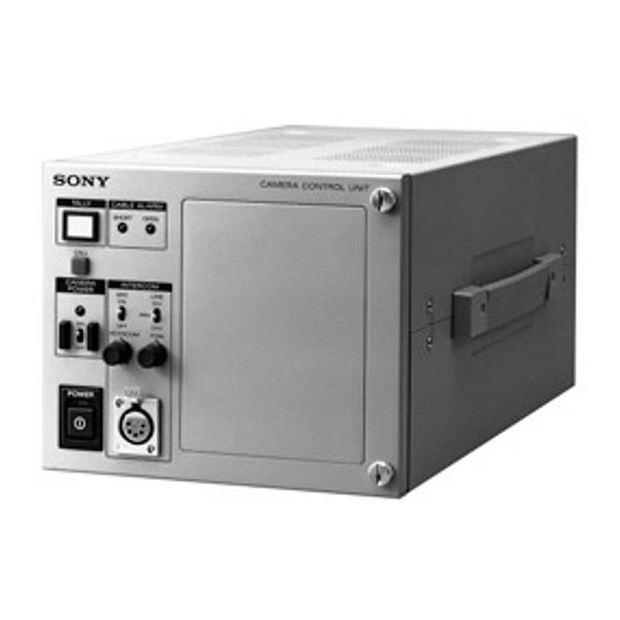
- Page 1 CAMERA CONTROL UNIT CCU-TX7 CAMERA CONTROL UNIT CCU-TX7P CAMERA OPERATION UNIT COU-TX7 SERVICE MANUAL Vol. 1 (1st Edition)
- Page 2 2. A battery-operated AC milliammeter. The Sony Corporation interdit formellement la copie de Data Precision 245 digital multimeter is quelque partie que ce soit de ce manuel ou son emploi suitable for this job. pour tout autre but que des opérations ou entretiens de 3.
- Page 3 Purpose of this manual This manual is the Service Manual Vol. 1 of the CAMERA CONTROL UNIT CCU-TX7 (for NTSC) and CCU-TX7P (for PAL), and also CAMERA OPERATION UNIT COU- TX7. This manual contains the operation manual related to the operations of this equipment, the replacement of the parts and adjustments.
-
Page 4: Table Of Contents
TABLE OF CONTENTS 1. OPERATING INSTRUCTIONS 4-2-11. R Level Adjustment ........4-8 4-2-12. B Level Adjustment ........4-8 2. INSTALLATION 4-2-13. WF OUT R/B DC OFFSET Adjustment ..4-9 4-2-14. Carrier Balance Adjustment ......4-9 2-1. CONNECTORS AND CABLES ......2-1 4-2-15. - Page 5 http://getMANUAL.com 4-7. TRIAX Interface System Adjustment ....4-26 4-7-1. Frequency Set Adjustment ......4-26 4-7-2. INCOM Deviation Adjustment ....4-27 4-7-3. PGM Deviation Adjustment ......4-27 4-7-4. INCOM Demodulation Adjustment .... 4-28 4-7-5. INCOM Level Adjustment ......4-28 4-7-6. MIC 1 Demodulation Adjustment ....4-29 4-7-7.
-
Page 6: Operating Instructions
3-859-845-11(1) Camera Control Unit Operating Instructions Before operating the unit, please read this manual thoroughly and retain it for future reference. CCU-TX7/TX7P © 1997 by Sony Corporation... - Page 7 Table of Contents For the customers in the USA WARNING This equipment has been tested and found to comply with the limits for a Class A digital device, pursuant to Part 15 of Overview ................4 To prevent fire or shock hazard, do not the FCC Rules.
-
Page 8: Overview
Overview Product Features Connections The CCU-TX7/TX7P is a camera control unit that Examples of how to connect other devices to this unit • Some of the video camera’s switches and buttons connects to DXC-637 Series and DXC-D30 Series are shown in the following. may not operate while the CCU-TX7/TX7P is Color Video Cameras via the CA-TX7/TX7P Camera connected to it. -
Page 9: Installing The Camera Operation Unit
Overview When using two CCU-TX7/TX7P units Installing the Camera Operation Unit The following describes how to fit the optional COU- TX7 Camera Operation Unit to the CCU-TX7/TX7P’s Switcher, video monitor, etc. front panel. DXC-D30/D30P Y/R–Y/B–Y,R/G/B,Y/C Open the CCU-TX7/TX7P’s front panel. Chroma keyer GENLOCK Reference sync signal... -
Page 10: Location And Function Of Parts
Location and Function of Parts You can then talk with the operator via the intercom. Various switches, adjustment knobs, and connectors CCU-TX7/TX7P switches and knobs This button also lights when the CALL button is are located on the front panel, rear panel, and also on pressed on the camera adaptor or remote control panel. - Page 11 Location and Function of Parts 3 SHUTTER setting section 4 WHITE/BLACK BALANCE control section Camera operation unit switches and knobs Display BLACK AUTO/ WHITE/BLACK switch and MANUAL indicators switch 1 OUTPUT switch 7 GAIN switch SHUTTER WHITE AUTO/PRE/MANUAL switch C.SCAN OPERATE OUTPUT GAIN...
- Page 12 Location and Function of Parts !™ IRIS control section !£ DIP switch WHITE AUTO/PRE/MANUAL (white balance WHITE (white balance) knob (blue) auto/preset/manual) switch When the WHITE AUTO/PRE/MANUAL switch is Use the four switches numbered 1 to 4 to make the Use this switch to select the white balance adjustment set to MANUAL, this knob can be used to adjust the following settings.
-
Page 13: Rear Panel
Location and Function of Parts 8 RS232C connectors (D-sub 25-pin) WF (waveform monitor output) connector Rear Panel There are two connectors, CH1 and CH2. You can use Use this connector to output a video signal to a waveform monitor. Use the MONITOR SELECT these connectors to connect a personal computer to control the video camera. -
Page 14: Internal Board Switches And Knobs
Location and Function of Parts !™ MIC OUT connectors (XLR 3-pin) Internal Board Switches and Knobs Use these connectors to output microphone signals (CH1 and CH2) from the connected video camera. For details concerning adjustment of internal board Loosen the two screws on the right side of the front switches and knobs, contact a Sony service representative. - Page 15 http://getMANUAL.com Location and Function of Parts 1 ES-20 board 2 AA-90 board INTERCOM (intercom system select) switches PANEL (panel control) switch Use these switches to select the type of external When the COU-TX7 Camera Operation Unit has been intercom system to be used. Set the upper switch to installed on this unit while the RCP-TX7 Remote 4W if no external intercom is connected.
-
Page 16: Notes On Use
BNC type (2 each) CCU-TX7: 120 VAC, 50/60 Hz Y: 1.0 Vp-p, 75 Ω 104°F)). CCU-TX7P: 220 to 240 VAC, 50/ Note that in summer the temperature in a car with the After use C: 286 mV (CCU-TX7)/300 mV 60 Hz, 0.45 A (CCU-TX7P) (burst), 75 Ω... -
Page 17: Installation
: 1.0 V p-p • R-Y (BNC) : 700 mV p-p (for CCU-TX7) (EXTERNAL VIEW) : 525 mV p-p (for CCU-TX7P) • B-Y (BNC) : 700 mV p-p (for CCU-TX7) (0 dBu = 0.775 Vrms) : 525 mV p-p (for CCU-TX7P) - Page 18 • INTERCOM/TALLY (D-Sub 25P, FEMALE) • RS-232C CH1/CH2 (D-Sub 25P, FEMALE) (EXTERNAL VIEW) (EXTERNAL VIEW) (0 dBu = 0.775 Vrms) (0 dBu = 0.775 Vrms) Signal Specifications Signal Specifications GREEN TALLY (Y) IN ON : 24 V DC/TTL (H)/SHORT CHASSHIS GND This is based on RS-232C GREEN TALLY (X) IN OFF : 0 V DC/TTL (L)/OPEN TXDATA...
- Page 19 2. Front panel • PGM IN (XLR 3P, FEMALE) • INTERCOM (XLR 5P, FEMALE) (EXTERNAL VIEW) (EXTERNAL VIEW) Signal Specifications PGM IN (G) 0 dBu/ -20 dBu (0 dBu = 0.775 Vrms) PGM IN (X) (Selectable with PGM switch on AA-90 Signal Specifications PGM IN (Y)
-
Page 20: Connection Connector
2-1-2. Connection Connector 2-1-3. Wiring Diagram for Cable Use the connectors below or the equivalent at its tip when • CCA-7 cable cables are connected to each connector on the connector panel during installation and servicing. Blue White Connector name Connected connector/cable Orange GENLOCK VIDEO 1, 2... -
Page 21: Coax Connector
2-3. COAX CONNECTOR 2-4. OPERATING ENVIRONMENT The COAX connector (BNC type) can be used for connection Operating temperature : +5 ˚C to +40 ˚C : -20 ˚C to +55 ˚C between the CCU and the CA with a BNC cable instead of a Storage temperature triaxial cable. -
Page 22: Mounting On 19-Inch Rack
2-5. MOUNTING ON 19-INCH RACK Two CCU-550s can be mounted on a 19-inch EIA standard rack in parallel by using rack mount adaptor RMM-TXC7 (optional). Mounting 1. Tighten the four rack mount screws. RMM-TXC7 B5 screws (60 mm or more long) 2. -
Page 23: Switch Functions On Board
2-6. SWITCH FUNCTIONS ON BOARD • S2002 (PROMPT SELECT TX/RX) TX : When selecting the TX mode, the CCU modulates CT-181 board the VBS signal input to the PROMPT VIDEO IN connector on the CCU-TX7/TX7P, and modulated signal is sent to the CA-TX7/TX7P. E1001 TP2006 RET FREQ... - Page 24 AA-90 board T201 T301 AA-90 TP44 PGM IN TP12 T401 –20dB TP15 MIC 1 LEVEL –20dB LV101 TP43 TONE TUNE 5.6M TUNE MIC 2 LEVEL –20dB MIC TEST LV21 CH-1 2.5M CCU DATA LV61 LV41 CH-2 4.3M 3.6M LEVEL IND TP46 LV1 3.0M INTER COM...
- Page 25 http://getMANUAL.com YD-26 board TP26 SAMPL GATE TP10 SAMPL S/H Y AGC CONT TP11 Y OFFSET ADJ Y LEVEL YD-26 TP4 TP7 Y 2'nd AGC Y RF TUNE VCO DC SET RV17 TP12 BLACK S/H SYNC S/H R-Y LEVEL TP17 RV12 C 2'nd AGC B-Y LEVEL R-Y CARR BAL...
- Page 26 ES-20 board Y LEVEL (VBS) RV804 SYNC LEVEL (VBS) CHROMA LEVEL SYNC WIDTH RV803 RV802 RV810 ES-20 PHASE Y LEVEL(COMP) RV800 RV801 H PHASE SYNC PHASE SYNC LEVEL(COMP) Y SETUP LEVEL (NTSC ONLY) SC PHASE SC FREQUENCY 180° RV812 B-Y LEVEL OUT PUT 1 SC-H PHASE R/G/B...
-
Page 27: Service Information
SECTION 3 SERVICE INFORMATION 3-1. BOARD LAYOUT CN-1327 board IO-140 board Step shaft MB-693 board +K 3x6 CN-1351 board CT-181 board CN-1325 board AA-90 board YD-26 board ES-20 board Connector Connector AU-234 board CN-1328 board CN-1350 board Front panel AU-234 board Switching regulator 3-2. -
Page 28: Replacement Of Switching Regulator
3-2-2. Replacement of Switching Regulator 3-2-3. Installation of COU-TX7 1. Remove the top and bottom covers. (Refer to "3-2-1. As for installing of COU-TX7, refer to "Installing the Camera Removal of Cabinet".) Operation Unit" of service manual SECTION 1. 2. Remove four screws and disconnect CN1 on the IO-140 board and CN10, CN19 and CN20 on the MB-693 board. -
Page 29: Circuit Description
3-3. CIRCUIT DESCRIPTION YD-26 board YD-26 board demodulates Y, R-Y, B-Y, CAM SYNC and CT-181 board SKIN GATE. This circuit consists of cable length detection CT-181 board employs RF system circuit that is consists of circuit, cable length compensation circuit and these RETURN VIDEO modulation circuit and PROMPT VIDEO demodulation circuits. -
Page 30: Adjustment
SECTION 4 ADJUSTMENT 4-1. Preparation 4-1-3. Notes on Adjustment 4-1-1. Equipment Required CAUTION • When performing STAIR CASE adjustment, connect the • Oscilloscope (more than 300 MHz) WF MODE connector of CCU-TX7/TX7P rear panel to Tektronix 2465 or equivalent the remote control connector of waveform monitor with •... -
Page 31: Connections
4-1-5. Connections CAMERA CONTROL UNIT CCU-TX7/TX7P (CAMERA OPERATION UNIT CAMERA COU-TX7/TX7P) ADAPTOR CA-TX7/TX7P Waveform monitor A-ch TRIAX CABLE (30~750m) Vector scope COLOR VIDEO CAMERA DXC-D30/D30P DXC-637/637P CCA-TX7 CABLE 75Ω Color monitor 75Ω RCP-TX7 Audio connections Audio generator Audio generator LEVEL LEVEL 600Ω... -
Page 32: Video Signal System Adjustment
4-2. Video Signal System Adjustment 4-2-2. CAM H Phase Adjustment 4-2-1. Sub-carrier Frequency Check Equipment : Oscilloscope (CHOP mode) To be extended : ES-20 board Note : Check that the GEN LOCK IN connector of CCU- Preparation : TX7/TX7P rear panel is no signal. •... -
Page 33: H Phase Adjustment
4-2-3. H Phase Adjustment 4-2-4. SYNC Phase Adjustment Equipment : Oscilloscope (CHOP mode) Object : Overall white Video signal generator (white portion of the pattern box) Equipment : Waveform monitor (Color Bar signal) To be extended : ES-20 board To be extended : ES-20 board Preparation : Preparation : •... -
Page 34: Int Sc Phase Adjustment
4-2-5. INT SC Phase Adjustment 4-2-6. Y CLAMP Adjustment Note : The SC-H phase measurement equipment (Tektronix : Equipment : Oscilloscope To be extended : ES-20 board Waveform monitor 1765 or equivalent) is used for Preparation : this adjustment. In case of using another measurement equipment, read its instruction manual carefully and •... -
Page 35: Y Out (Comp) Level Adjustment
http://getMANUAL.com 4-2-7. Y OUT (COMP) Level Adjustment 4-2-8. Y OUT (VBS) Level Adjustment Equipment : Waveform monitor Equipment : Waveform monitor To be extended : ES-20 board To be extended : ES-20 board Preparation : Preparation : • Select the BARS mode on the RCP-TX7 or COU-TX7. •... -
Page 36: R-Y/B-Y White Black Balance
4-2-9. R-Y/B-Y White Black Balance 4-2-10. G Level Adjustment Adjustment Equipment : Waveform monitor Equipment : Oscilloscope To be extended : ES-20 board To be extended : ES-20 board Preparation : Preparation : • Select the BARS mode on the RCP-TX7 or COU-TX7. •... -
Page 37: R Level Adjustment
4-2-11. R Level Adjustment 4-2-12. B Level Adjustment Equipment : Waveform monitor Equipment : Waveform monitor To be extended : ES-20 board To be extended : ES-20 board Preparation : Preparation : • Select the BARS mode on the RCP-TX7 or COU-TX7. •... -
Page 38: Wf Out R/B Dc Offset Adjustment
4-2-13. WF OUT R/B DC OFFSET Adjustment 4-2-14. Carrier Balance Adjustment Equipment : Waveform monitor Equipment : Vectorscope (MAX GAIN) To be extended : ES-20 board To be extended : ES-20 board Preparation : Preparation : • Select the BARS mode on the RCP-TX7. •... -
Page 39: Color Vector Adjustment
4-2-15. Color Vector Adjustment 4-2-16. R-Y/B-Y OUT Level Adjustment Equipment : Vectorscope, Waveform monitor Equipment : Oscilloscope To be extended : ES-20 board To be extended : ES-20 board Preparation : Preparation : • GAIN Switch/vectorscope → "75% CAL" • Select the BARS mode on the RCP-TX7 or COU-TX7. •... -
Page 40: Vbs Out Level Adjustment
4-2-17. VBS OUT Level Adjustment 4-2-18. STAIR CASE Adjustment Equipment : Waveform monitor Note : This adjustment is for temporary adjustment when To be extended : ES-20 board repairing the STAIR CASE block. In the system Preparation : set up, the readjustment is required to match the •... -
Page 41: Y Cable Compensation System Adjustment
4-3. Y Cable Compensation System 4-3-2. BLACK Pulse Width Adjustment Adjustment Equipment : Oscilloscope 4-3-1. SYNC SEP Adjustment To be extended : YD-26 board Test point : TP5 (GND: E2)/YD-26 board Equipment : Oscilloscope Adjusting point : 1RV2 (BLACK S/H)/YD-26 board : T = 1.7 ±... -
Page 42: Sync Sample Hold Pulse Width
4-3-3. SYNC Sample Hold Pulse Width 4-3-4. 22.5 MHz VCO DC Set Adjustment Adjustment Note : Make sure that 45MHz frequency on the YM-15 Equipment : Oscilloscope board (CA-TX7/TX7P) should be correct. To be extended : YD-26 board Test point : TP8 (GND: E2)/YD-26 board Equipment : Oscilloscope... -
Page 43: Sample Pulse Width Adjustment
4-3-5. Sample Pulse Width Adjustment 4-3-6. Sample Pulse V Gate Width Adjustment Equipment : Oscilloscope To be extended : YD-26 board Equipment : Oscilloscope Test point : TP7 (GND: E2)/YD-26 board To be extended : YD-26 board Adjusting point : 1RV4 (SAMPLE S/H)/YD-26 board Test point : TP7 (GND: E2)/YD-26 board : T = 40.0 ±... -
Page 44: Mhz Carrier Level Adjustment
4-3-7. 22.5 MHz Carrier Level Adjustment 4-3-8. Y DEMOD Carrier Balance Adjustment Equipment : Oscilloscope Equipment : Oscilloscope To be extended : YD-26 board To be extended : YD-26 board Test point : TP10 (GND: E5)/YD-26 board Preparation : Adjusting point : 1RV7 (Y CARR LEVEL)/ •... -
Page 45: Y Offset Adjustment
http://getMANUAL.com 4-3-9. Y OFFSET Adjustment 4-3-11. Y 1st AGC Adjustment Equipment : Oscilloscope Equipment : Oscilloscope To be extended : YD-26 board To be extended : YD-26 board Test point : TP11 (GND: E6)/YD-26 board Preparation : • S1 (AUTO/MANU)/YD-26 board → "AUTO" Adjusting point : 1RV24 (Y OFFSET ADJ)/ •... -
Page 46: Y Output Level Adjustment
4-4. CHROMA Cable Compensation 4-3-12. Y Output Level Adjustment System Adjustment Equipment : Oscilloscope 4-4-1. 45 MHz Carrier Level Adjustment To be extended : YD-26 board Preparation • S3 (Y 2nd AGC)/YD-26 board → "ON" Equipment : Oscilloscope Test point : TP11 (GND: E6)/YD-26 board To be extended : YD-26 board Adjusting point : 1RV9 (Y LEVEL)/YD-26 board... -
Page 47: C Pll Set Adjustment
4-4-2. C PLL Set Adjustment 4-4-3. B-Y DEMOD Carrier Balance Adjustment Note : Make sure that 45 MHz frequency on the YM-15 Equipment : Oscilloscope board (CA-TX7/TX7P) is correct. To be extended : YD-26 board Equipment : Oscilloscope Preparation : •... -
Page 48: B-Y Crosstalk Adjustment
4-4-4. B-Y Crosstalk Adjustment 4-4-5. C 1st AGC Adjustment Note : Make sure that 45 MHz frequency on the YM-15 Equipment : Oscilloscope To be extended : YD-26 board board (CA-TX7/TX7P) is correct. Preparation : • S1 (AUTO/MANU)/YD-26 board → "AUTO" Equipment : Oscilloscope •... -
Page 49: B-Y Out Level Adjustment
4-4-6. B-Y OUT Level Adjustment 4-4-7. R-Y DEMOD Carrier Balance Adjustment Equipment : Oscilloscope To be extended : YD-26 board Equipment : Oscilloscope Preparation : To be extended : YD-26 board • S4 (C 2nd AGC)/YD-26 board → "ON" Test point : TP18 (GND: E9)/YD-26 board Test point : TP17 (GND: E8)/YD-26 board... -
Page 50: R-Y Crosstalk Adjustment
4-4-8. R-Y Crosstalk Adjustment 4-4-9. R-Y OUT Level Adjustment Note : Make sure that 45 MHz frequency on the YM-15 Equipment : Oscilloscope To be extended : YD-26 board board (CA-TX7/TX7P) is correct. Preparation : • S4 (C 2nd AGC)/YD-26 board → "ON" Equipment : Oscilloscope To be extended : YD-26 board... -
Page 51: Return Video Cable Compensation System Adjustment
4-5. RETURN VIDEO Cable Compensation 4-5-2. Return Video Deviation Adjustment System Adjustment Equipment : Spectrum analyzer 4-5-1. Return Video Carrier Frequency To be extended : CT-181 board Adjustment Preparation : • Input 10 STEP signal (sub-carrier : OFF) of video signal Equipment : Spectrum analyzer generator to RETURN-1 connector (75 Z termination, 1.0... -
Page 52: Prompt Video Cable Compensation System Adjustment
4-6. PROMPT VIDEO Cable Compensation System Adjustment 4-6-1. TX PROMPT VIDEO Demodulation Adjustment Note : When performing this adjustment, the TRIAX cable less than 300 m should be used. Equipment : Waveform monitor, Video signal generator (10 STEP signal) To be extended : CT-181 board Preparation : •... -
Page 53: Rx Prompt Video Demod
4-6-2. RX PROMPT VIDEO Demod. 2. Adjust 1LV2 (PROMPT FREQ)/CT-181 board so that Adjustment the frequency response at 6 MHz portion is minimum. Note : • Perform this adjustment only when replacing 1LV2 (PROMPT FREQ) or 1LV3 (PROMPT TUNE)/CT-181 board. When performing this adjustment, the TRIX cable less than 300 m should be used. -
Page 54: Adjustment
4-6-3. RX PROMPT VIDEO RF AGC Adjustment Note : When performing this adjustment, the TRIAX cable Note : After this adjustment is completed, set the switches 50 m to 150 m should be used. as follows. Adjustment of CA-TX7 /TX7P must be completed. •... -
Page 55: Rx Prompt Video Level Adjustment
http://getMANUAL.com 4-7. TRIAX Interface System Adjustment 4-6-4. RX PROMPT VIDEO Level Adjustment 4-7-1. Frequency Set Adjustment Note : When performing this adjustment, the TRIAX less than 300 m should be used. Note : Check to see that no signal is input to the INCOM Adjustment of CA-TX7/TX7P must be completed. -
Page 56: Incom Deviation Adjustment
4-7-2. INCOM Deviation Adjustment 4-7-3. PGM Deviation Adjustment Equipment : Spectrum analyzer, Oscilloscope, Equipment : Spectrum analyzer, Oscilloscope, Audio generator Audio generator To be extended : AA-90 board To be extended : AA-90 board Preparations : Preparetions : 1. INTERCOM CH1/CH2 switch (CA-TX7/TX7P side panel) 1. -
Page 57: Incom Demodulation Adjustment
4-7-4. INCOM Demodulation Adjustment 4-7-5. INCOM Level Adjustment Note : Perform this adjustment only when replacing 1T401/ Equipment : Oscilloscope, Audio generator To be extended : AA-90 board AA-90 board. FM-15 board (CA-TX7/TX7P) Equipment : Oscilloscope, Audio generator Preparetion : To be extended : AA-90 board 1. -
Page 58: Mic 1 Demodulation Adjustment
4-7-6. MIC 1 Demodulation Adjustment 4-7-7. MIC 1 Level Adjustment Note : Perform this adjustment only when replacing 1T201/ Equipment : Oscilloscope, Audio generator To be extended : AA-90 board AA-90 board. AFM-15 board (CA-TX7/TX7P) Equipment : Oscilloscope, Audio generator Preparations : To be extended : AA-90 board 1. -
Page 59: Mic 2 Demodulation Adjustment
4-7-8. MIC 2 Demodulation Adjustment 4-7-9. MIC 2 Level Adjustment Note : Perform this adjustment only when replacing 1T301/ Equipment : Oscilloscope, Audio generator To be extended : AA-90 board AA-90 board. AFM-15 board (CA-TX7/TX7P) Equipment : Oscilloscope, Audio generator Preparations : To be extended : AA-90 board 1. -
Page 60: Cam Data Demodulation Adjustment
4-7-10. CAM DATA Demodulation Adjustment 4-7-11. CAM TONE Adjustment Notes : Notes : • This adjustment for the following cameras must be • This adjustment for the following cameras must be completed before this adjustment. completed before this adjustment. [For NTSC] DXC-637 or DXC-D30 [For NTSC] DXC-637 or DXC-D30 [For PAL] DXC-637P or DXC-30P... - Page 61 CCU-TX7 (UC) Printed in Japan Sony Corporation CCU-TX7P (CE) 1997. 6 11 9-977-286-11 Image & Sound Communication Company © 1997 Published by Engineering Services Dept.
Need help?
Do you have a question about the CCU-TX7P and is the answer not in the manual?
Questions and answers